48
LNG
INDUSTRY
MARCH
2016
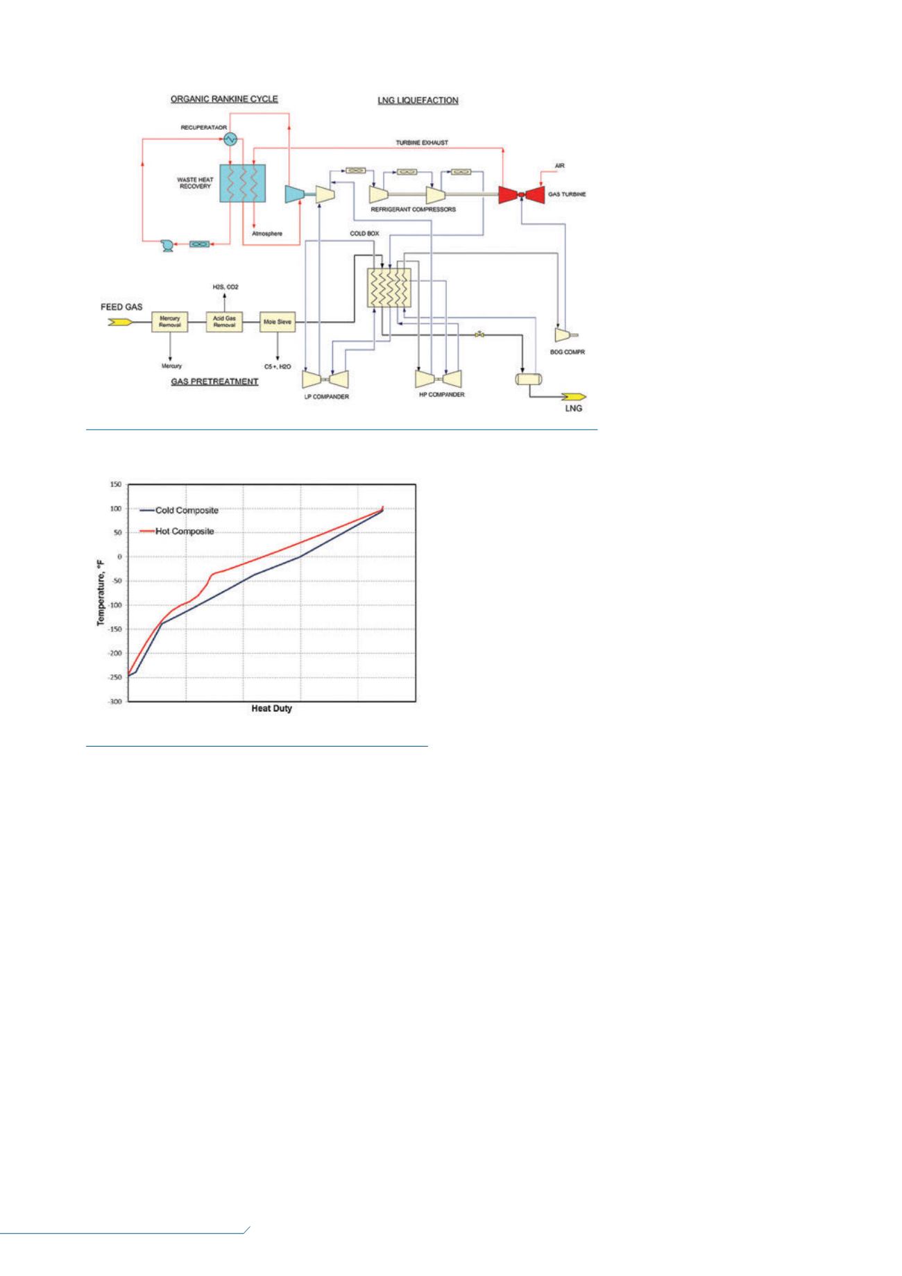
Integration to SMR
liquefaction cycle
The configuration of the SMR cycle
1
has been integrated
with the ORC power plant as shown in Figure 1. As described
previously, the high pressure lean gas is treated and dried,
with its C
5+
content removed in the molecular sieve unit. The
treated gas is chilled, condensed and subcooled in a cold box
to approximately -245°F using refrigeration produced by the
SMR cycle. The cold box uses a multi-pass brazed aluminium
heat exchanger to produce a subcooled LNG and refrigerant
at high pressure. The high pressure subcooled refrigerant is
let down by the Joule-Thomson effect and chilled, forming
the cooling medium for the liquefaction process. The high
pressure subcooled LNG is then letdown in pressure to close
to atmospheric pressure for LNG storage. The flashed vapour,
or boil-off gas (BOG), is heat exchanged in the cold box for
recovery of the refrigeration content prior to being used as fuel
gas to the gas turbine. To improve cycle efficiency, a hydraulic
turbine can be used for recovery of power and refrigeration.
The SMR cycle uses a single working fluid composed of
multiple hydrocarbons and nitrogen. The selected refrigerant
composition depends on the feed gas composition and the
liquefaction pressure. Refrigerant
composition is chosen so that it
has an evaporation curve that
matches the cooling curve of the
natural gas with minimum
temperature difference. A small
temperature difference reduces
entropy generation and, therefore,
improves thermodynamic
efficiency and reduces power
consumption. As shown in
Figure 2, the hot composite
(natural gas) and the cold
composite (SMR) heat curves can
be matched closely, particularly in
the condensing and subcooling
section of the exchanger.
The SMR compression system
typically uses three compression
stages with inter-stage coolers,
with the first stage driven by the
expander in the ORC plant.
Depending on the refrigerant composition, some of the
butane and pentane components will be condensed in the
inter-stage that must be removed before further compression.
The condensate is removed in a separator and pumped to
feed the heat exchanger. Since the air cooler is designed for
summer operation, the outlet temperature will drop during
winter operation, which will result in excessive condensation.
The SMR cycle air cooler must be controlled using variable
speed fans, and in extreme cold weather, some of the air fan
motors must be shutdown to avoid over cooling.
Operation of the SMR requires operator attention. The
process requires a supply of different hydrocarbons and
nitrogen. The refrigerant composition must be monitored and
adjusted to maintain high efficiency, particularly when the
feed gas composition changes.
Integration to expander
liquefaction cycle
While the SMR process is an efficient liquefaction process,
the liquid hydrocarbon inventory in the system is a potential
hazard for offshore applications. The gas-phase expander
cycle, which has been used for small LNG plants and BOG
liquefaction, is a viable option. With the recent advances
in expander and compressor technology, coupled with the
improved process configurations, the thermal efficiency of the
gas expander cycle is close to the SMR process.
The gas expander cycle efficiency is a function of the
compressor power consumption and the expander power
generation. Expander efficiency of over 86% is now common,
and compressor efficiency of over 80% is also available.
Ambient air temperature is another parameter that impacts
the expander cycle efficiency. In cold climate operation, the
compressor suction temperature can be lowered, which
reduces the compression horsepower. On the other hand, hot
climate operation raises the compressor suction temperature,
which increases the compression horsepower. The cold
climate operation cycle efficiency can be 10 – 15% higher than
the warm climate operation.
The expander cycle is a reversed Brayton Cycle that uses
gas expansion to generate power to operate the refrigeration
Figure 3.
ORC and expander LNG liquefaction.
Figure 4.
Composite heat curves for expander process.


