58
LNG
INDUSTRY
MARCH
2016
Plate-fin heat exchanger
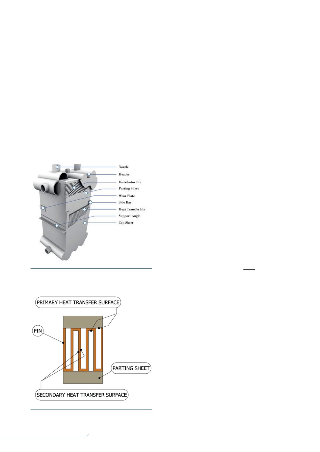
A BAHX, as defined by ALPEMA
1
, consists of a block (core) of
alternating layers (passages) of corrugated fins. The layers are
separated from each other by parting sheets and sealed along
the edges by means of side bars, and are provided with inlet
and outlet ports for the streams. The block is bounded by cap
sheets at the top and bottom. A figure of a BAHX with some
segments cut away so that the internals can be seen
2
is shown
in Figure 1.
Heat transfer and pressure
drop
While a BAHX is typically larger than a vehicle, it is important
to remember that all heat transfer is local at the millimeter
level. Heat transfer in a BAHX takes place almost entirely by a
convection mechanism between the fluid and the metal, which
is comprised of a fin and parting sheet. A fin height is typically
6 – 10 mm and a fin spacing is typically 1 – 3 mm, yielding
a channel size range of 1 mm x 6 mm to 3 mm x 10 mm. An
example of the cross section of a plate-fin structure is shown
in Figure 2.
Once a fluid is flowing in a channel, there is usually very
little communication with the fluid in the other channels.
The sensitivity of heat transfer to the flow distribution
among channels is examined in the following analysis. The
governing convection equation is:
Where q is the amount of heat transferred, h is the
convective heat transfer coefficient, A
p
is the primary heat
transfer surface area,
η
is the fin efficiency, A
s
is the secondary
heat transfer area, T
w
is the wall temperature, and T
b
is the fluid
bulk temperature.
For single phase heat transfer, the convective heat transfer
equation is:
Where j is the Colburn j factor (dimensionless heat transfer
coefficient), G is the mass velocity, Cp is the heat capacity, and
Pr is the Prandtl number. The Colburn j factor as a function of
flowrate can then be expressed in the form:
Where A is a constant with respect to the flowrate, Re is
the Reynolds number, and N is typically between -0.7 and -0.2.
For a given fixed geometry, removing thermophysical
properties and substituting equation 3 into equation 2 yields:
Pressure drop in a fin channel can be characterised by the
equation
3
:
Where Δp is the pressure drop, f is the Fanning friction
factor, L is the channel length, D is the hydraulic diameter, G is
the mass velocity, and ρ is the fluid density.
Test data for plate-fin structures
4
has found that f can be
expressed in the form:
Rearranged for the mass velocity:
Combining equation 7 with equation 4:
Equation 8 demonstrates that the heat transfer coefficient
is proportional to the pressure drop along a pressure drop
path, but, with the exponent of 0.3 to 0.4, the heat transfer
coefficient is not extremely sensitive to pressure drop changes.
Therefore, developing uniform heat transfer coefficients
should tend toward stability when fluctuations are
Figure 1.
Brazed aluminium heat exchanger sketch with some
segments cut away so the internals can be seen.
Equation 1: q = h (A
p
+
η
A
s
) (T
w
– T
b
)
Equation 2: h = j G Cp Pr
-2/3
Equation 3: j = A Re
N
Equation 4:
h
∝
G
(0.3 to 0.8)
Equation 5: Δp = 4f L G
2
D 2р
Equation 6: f = A Re
(-1.0 to -0.1)
Equation 7:
G
∝
Δp
(0.5 to 1.0)
Equation 8:
h
∝
Δp
(0.3 to 0.4)
Figure 2.
Cross section of a plate-fin layer.


