62
LNG
INDUSTRY
MARCH
2016
outlet distributor type; and different inlet vs outlet distributor
finning. The left hand side flow path and right hand side flow
path through the heat transfer finning (2) are identical.
Therefore, even flow distribution through the layer can be
promoted by increasing the pressure drop in the heat transfer
finning (2) relative to the pressure drop in the entry distribution
finning (1) and the exit distribution finning (3).
Commercially available software can calculate distribution
finning and heat transfer finning pressure losses. Chart designs
each stream’s layers to promote uniform flow distribution. As
this calculation is on a single layer basis, there are no scaling
issues when more layers are added. This technique has been
proven in service for the IPSMR process at plant sizes of
0.3 million tpy, and other LNG processes up to 5.2 million tpy.
Pitch
A pitch is a group of layers that are repeated a number of
times along the exchanger height. A pitch is generally the
basic group of layers that exchange heat with each other. A
typical pitch may only be 3 or 4 in. along the stack height. A
design goal for a pitch is to provide uniform heat transfer in the
pitch so that it is essentially an adiabatic entity. An example of
a six-layer pitch for a heat exchanger in an LNG application is
shown in Figure 4, where LPR is low pressure refrigerant and
HPR is high pressure refrigerant.
Chart calculates the heat transfer performance of the
exchanger (and, therefore, all of the pitches), utilising
commercially available software. While the pitch arrangement
varies significantly from design to design (BAHXs can have
anywhere between two to more than 20 streams), the general
concept is to maximise the number of essentially adiabatic,
and symmetric pitches, while minimising the overall BAHX
size.
Block
When the required volume of flow is more than one pitch can
handle, a stack of pitches is used to form a block. A block is a
collection of pitches stacked on top of one another up to the
maximum height that can be brazed into a single block. Very
little heat is exchanged between the different pitches in the
block when they are stacked together, since effort is made to
design the pitch per the criteria.
In scale-up, the number of pitches can be increased as
needed to meet the total flow requirement, as long as the flow
distribution entering each layer remains the same. As already
stated, it is desirable to design as much pressure drop into the
layer as allowed and minimise other losses.
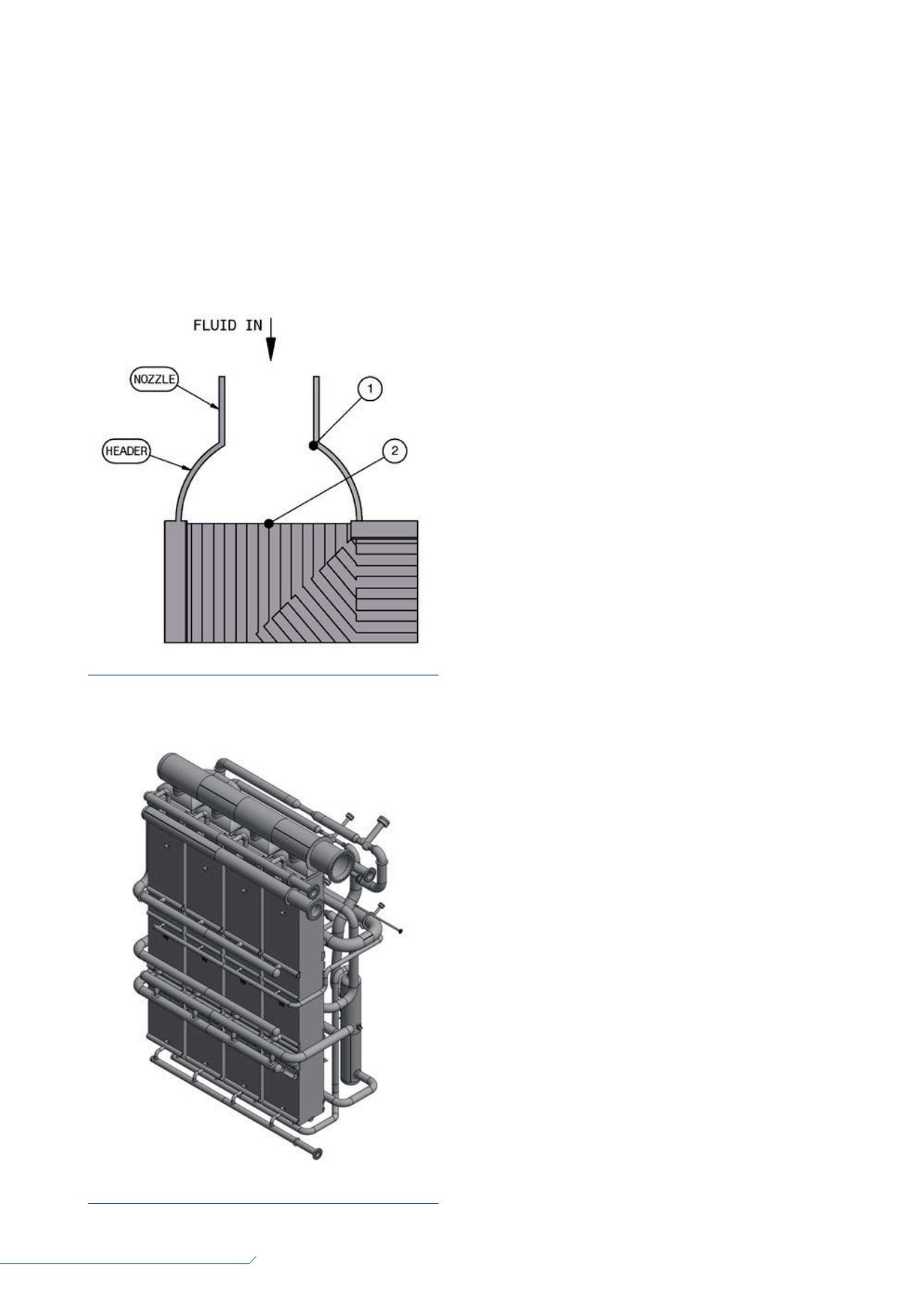
The nozzle is a stub pipe that is used to connect the
exchanger to the process piping. The nozzle connects to a
header, which is used to distribute the flow to the entry or exit
ports of the layers associated with that stream. There is an
expansion/contraction pressure loss associated with the
nozzle to header transition (1), and the header to port transition
(2), as shown in Figure 5. These pressure losses are calculated
in commercially available software.
Chart has methodology to analyse the distribution of flow
through the header to each individual pitch. It has calculated a
maximum mass flow difference of 4% between pitches for a
worst case exchanger design/operating case for the IPSMR
process. The maximum mass flow difference between pitches
for typical IPSMR designs is approximately 2% at design
flowrate.
Even distribution of the flow from the header to the
individual ports is achieved due to the negligible pressure drop
associated with flow through the header relative to the
pressure drop associated with the layers.
Battery
When the required volume of flow is more than one block
(one stack of pitches) can handle, multiple blocks of heat
exchangers are piped together in parallel to perform as one
heat exchanger. A group of blocks piped together is called a
Figure 5.
Example of a nozzle and header.
Figure 6.
Example of a multi-core battery.


