60
LNG
INDUSTRY
MARCH
2016
encountered, even when a heat exchanger design has
non-uniform pressure drop paths. The heat transfer coefficient
will vary less than the pressure drop or flowrate does.
Chart has proprietary fin designs, and Fanning friction f
data and Colburn j data for each fin design is based on
experimental testing. Commercial software is available to
calculate heat transfer and pressure drop performance for
these surfaces not only for single-phase fluids, but also for
two-phase fluids. Two-phase fluid heat transfer and pressure
drop principles are similar to single-phase fluids in that heat
transfer coefficients and pressure drop are also a function of
mass flux.
Distribution
In a BAHX, pressure drop of a single stream among multiple
flow paths will always be equal; flow to each path will vary
such that the pressure drop is the same. Therefore, to promote
uniform flow distribution, one must promote uniform pressure
drop. This also implies that one must have the ability to
calculate pressure drop for multiple flow paths. Chart has
the ability to rate heat transfer performance with varying
distribution of flow.
After performing many rating calculations, the company
has developed design guidelines on how uniform the flow
distribution must be and how to promote uniform flow
distribution. One technique that is useful in promoting uniform
distribution is to maximise the pressure drop in the location
where it is desired to have uniform flow (heat transfer finning,
two-phase distribution devices), while minimising other
pressure drops. The weak dependence of the heat transfer
coefficient as a function of flowrate helps to dampen
fluctuations and give uniform thermal performance in a BAHX,
as the heat transfer coefficient will generally vary less than the
pressure drop or flowrate does.
Achieving proper flow distribution through uniform
pressure drop is less predictable for two-phase streams. The
large density difference between the liquid phase and the
vapour phase in a two-phase stream can cause flow
maldistribution, particularly in parts of the exchanger with
large open cross sections, such as the manifolds and the
headers. Maldistribution of a two-phase stream can have a
significant impact on the actual exchanger performance vs the
simulated exchanger performance. The liquid will take
significantly less of the heat transfer area/volume due to its
higher density than the vapour phase, but the liquid phase has
higher heat transfer coefficients and a higher duty (in boiling
services). Therefore, assessing the impact of two-phase
distribution and developing design criteria to avoid two-phase
maldistribution is critical.
BAHX construction
Layer
A layer contains the flow of a particular stream, and the layers
are separated from each other by parting sheets (the outer
most layers are sealed on the ends by a cap sheet) and sealed
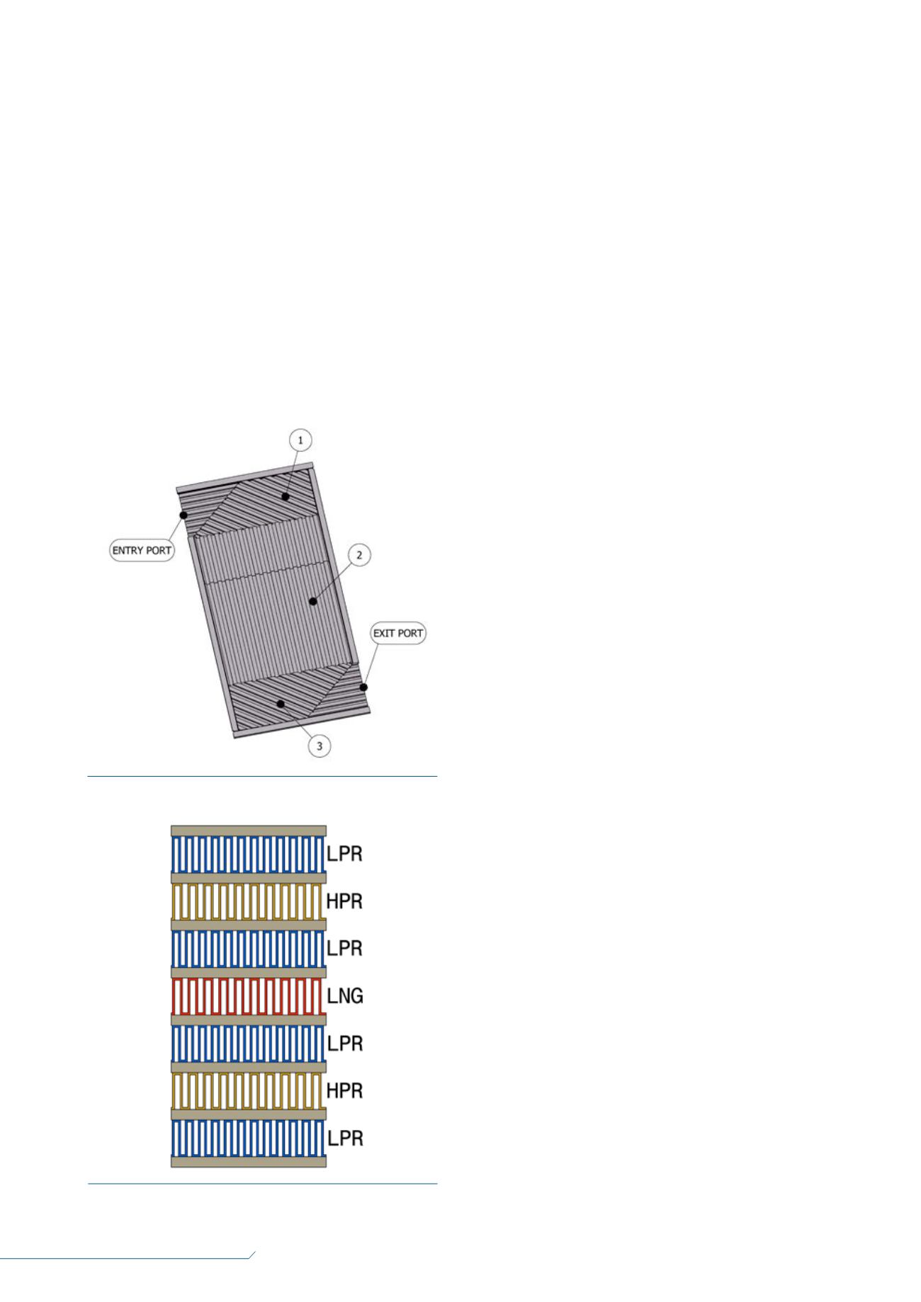
along the edges by side bars. As shown in Figure 3, a simple
layer has one stream with an entry port and distributor (1), a
heat transfer section (2), and an exit port and distributor (3).
Layers can be more complex, with multiple streams entering
a layer, but this example is limited to a simple layer. Layer
heights are typically 0.375 in. or 0.25 in. Layers are typically
4 ft wide and can be more than 20 ft long. The small layer
heights and variety of Chart fin geometries allow for optimised
velocities for each stream, unlike shell and tube exchangers,
in which the shell velocities are dictated by the tube bundle
geometry.
Flow maldistribution can occur due to the different flow
path along the left side vs the right side of the layer. For
example, in Figure 3, the left hand side will have a lower
frictional pressure loss in the entry distribution finning (1), and a
higher frictional pressure loss in the exit distribution finning (3)
relative to the right hand side. Therefore, it is desirable to
configure the entry distributor and the exit distributor to
balance the pressure drops through the left side vs the right
side flow paths. Note that balancing the left hand vs the right
hand pressure drops usually does not mean equivalent
distributor sizes, due to the following reasons: change in fluid
density with temperature and/or phase; different inlet vs
Figure 4.
Example of a pitch of layers in a heat exchanger in an
LNG application.
Figure 3.
Layer geometry.


