64
LNG
INDUSTRY
MARCH
2016
battery or assembly, and the connecting piping is referred to
as manifolds (Figure 6).
There is an expansion/contraction pressure loss
associated with the flow transition between the manifold and
nozzles. Commercially available software can be configured
using standard pipe network methodology to assess the
impact of flow distribution in the battery. Each block is
modeled as an individual exchanger in a pipe network. For
distribution purposes, it is desirable to design as much
pressure drop into the block as allowed and minimise the
piping losses in the manifolds (this minimises the flow
maldistribution from block to block).
Two-phase inlet distribution
Proper flow distribution for a two-phase inlet stream is less
predictable. Therefore, the following methodology to assess
the impact of two-phase maldistribution, and design criteria
to avoid two-phase maldistribution, is utilised for two-phase
streams in Chart’s IPSMR process. The first step is to assess
if a stream is in two-phase flow during any steady state
operating cases. If it is, then a flow regime analysis can be
performed to evaluate the flow characteristics of the stream.
For two-phase streams in a flow regime of concern (slug
flow, annular flow, etc.), two-phase maldistribution can occur.
Chart has developed a method to assess the potential effect
of two-phase maldistribution on the exchanger performance.
This method varies the amount of mixing of the liquid with the
vapour in the two-phase stream (from fully mixed to complete
phase separation), and measures the impact on the stream
temperature and thus the exchanger overall heat transfer
coefficient per unit area (UA). As the amount of liquid mixed
with the vapour decreases, the UA required increases due to
the changing mixture temperature pinching the cooling curve
of the exchanger.
In some cases, separating the liquid and vapour and then
introducing them in a controlled manner may be
advantageous. For two-phase streams where the UA increase
associated with the mixing percentage with no device or
perforated plate is detrimental, or for manifolded assemblies
of exchangers (where two-phase flow separation can occur
not only within the individual core header, but also within the
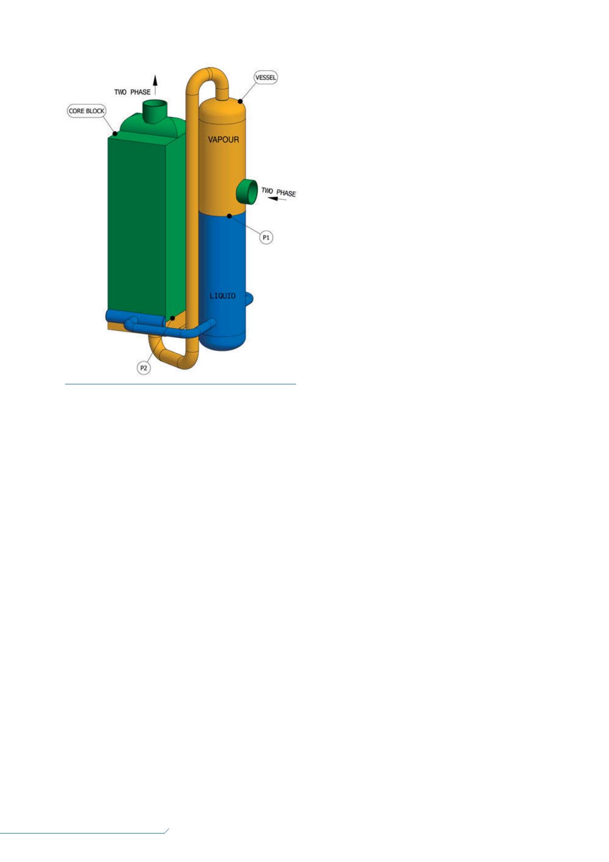
manifolding piping), a separation vessel and a two-phase
distribution device are used. Separating the liquid from the
vapour in a vessel, and then separately manifolding each
phase, ensures that equal amounts of liquid and vapour are
sent to every individual core block. Two-phase distribution
devices can be inserted at the inlet of any stream or any point
along the core length for any stream. A model of the layout of
the separation vessel, core, and piping is shown in Figure 7.
The liquid distribution is controlled by having most of the
liquid path pressure drop located in the liquid distribution
device. The liquid pressure drop, due to other factors (nozzles,
manifolds, piping), is kept low, so the liquid path pressure drop
from P1 to P2 is mostly at P2.
Chart has developed state-of-the art liquid distribution
devices that are incorporated within the core block for BAHX
designs for its IPSMR process. These liquid distribution devices
allow the introduction of mixed refrigerant (MR) into the heat
exchanger at precise locations along the heat exchanger to
‘tune’ the boiling refrigerant cooling curve and provide a very
efficient and robust single mixed refrigerant (SMR) process.
The vapour distribution device exit openings are sized to
keep the vapour velocity sufficiently high to prevent liquid
runback. The pressure drop, due to other factors (nozzles,
manifolds, piping), is kept low.
The liquid level in the vessel relative to the distribution
device is determined by the difference in pressure drop
between the liquid path and the vapour path from P1 to P2.
Since the two-phase distributor devices are static, the
range of liquid and vapour flowrates to meet design criteria
and maintain good distribution is limited. Chart has performed
numerous designs for its IPSMR process, and confirmed that a
flow range of 50 – 110% of design flow can be achieved with
uniform distribution.
The vessel diameter is sized to reduce the vapour velocity
in the vessel to prevent entrainment of the liquid by gravity
separation. For this application, a high degree of separation is
not required. The company has developed guidelines for
vessel sizing from a variety of sources, including HTRI
5
, GPSA
6
,
and Bechtel.
7
These criteria are used to design vessel
parameters, such as aspects of the vessel length and nozzle
sizes.
Conclusion
Thermal performance of a BAHX is dependent on promoting
uniform flow distribution. The essence of promoting uniform
distribution is to maximise the pressure drop in the location
where it is desired to have uniform flow distribution, while
minimising other pressure drops. For single-phase flow, the
heat transfer coefficient typically varies less than the pressure
drop or flowrate does, helping to promote uniform thermal
performance.
Commercially defined methodology and commercially
available software can be configured to evaluate the impact of
Figure 7.
Layout of separation vessel, core and piping.


