50
LNG
INDUSTRY
SEPTEMBER
2016
Deepwater intake solution
The liquefaction process requires large volumes of cooling
water. As a reference point, Shell’s
Prelude
FLNG facility
offshore Australia is designed for a cooling water intake
capacity of 50 000 m
3
/hr.
1
Prelude
will be installed at 250 m
water depth, with surface temperatures in the range of 25°C
and water intake located 150 m below the surface.
Reduced cooling water temperature gives an
approximately 1% increase in liquefaction process capacity per
degree Celsius temperature reduction. If intake air to gas
turbine drivers is also cooled by cold seawater, then the turbine
power output can be increased by approximately 1.5% per
degree Celsius air temperature reduction. Combining these two
effects, LNG production can typically be increased by 20% for a
tropical deepwater FLNG unit using the same gas turbine
drivers.
2
For a 2500 mwater depth case, Aker Solutions and Statoil
have conceptually designed an FLNG water intake system that
fetches cooling water from a water depth of 500 – 700 m. With
this system, there is the potential to reduce the cooling water
temperature by 15 – 20°C and increase the process efficiency
correspondingly. The Statoil FLNG case includes a bow turret
moored ship with a length of more than 400 m and an LNG
capacity of 3 – 3.5 million tpy, located in ~25°C surface
temperatures. The estimated cooling water requirement is
35 000 m
3
/hr taken from 500 mwater depths. This water
intake volume requirement corresponds to 700 full size
semi-trailers with water per hour – i.e. one semi-trailer every
5 sec. – necessitating large capacity suction pipes. A concept
with two single mounted steel risers with a diameter of up to
64 in. minimises implications on the ship design and process
layout.
System description
The water intake risers are mounted in sea chests aft on the
FLNG vessel – one on the starboard side and one on the port
side.
The material selected is carbon steel, with a minimum yield
strength of 415 MPa. The 64 in. riser pipes have a nominal wall
thickness of 20 mm. The outside steel surfaces are corrosion
protected both by anodes and coating, while the internal
surfaces are protected by a thermal sprayed aluminium coating.
The water intake risers are assembled from 24 m long
standard joints with flanged connections. One 500 m long
water intake riser weighs approximately 515 t in air and 395 t
when installed and submerged in seawater.
A pressure head loss of 4.5 m is assessed for 35 000 m
3
/hr
of cold seawater flowing in two 64 in. risers where the internal
diameter is reduced to 40 in. locally at hang-off.
Six dry mounted pumps (including one spare) installed in
pump rooms are the base case. Each pump has a capacity of
7000 m
3
/hr. Alternatively, submerged caisson pumps can be
Figure 1.
Floating LNG (FLNG) vessel with two 500 m deep
water intake risers.
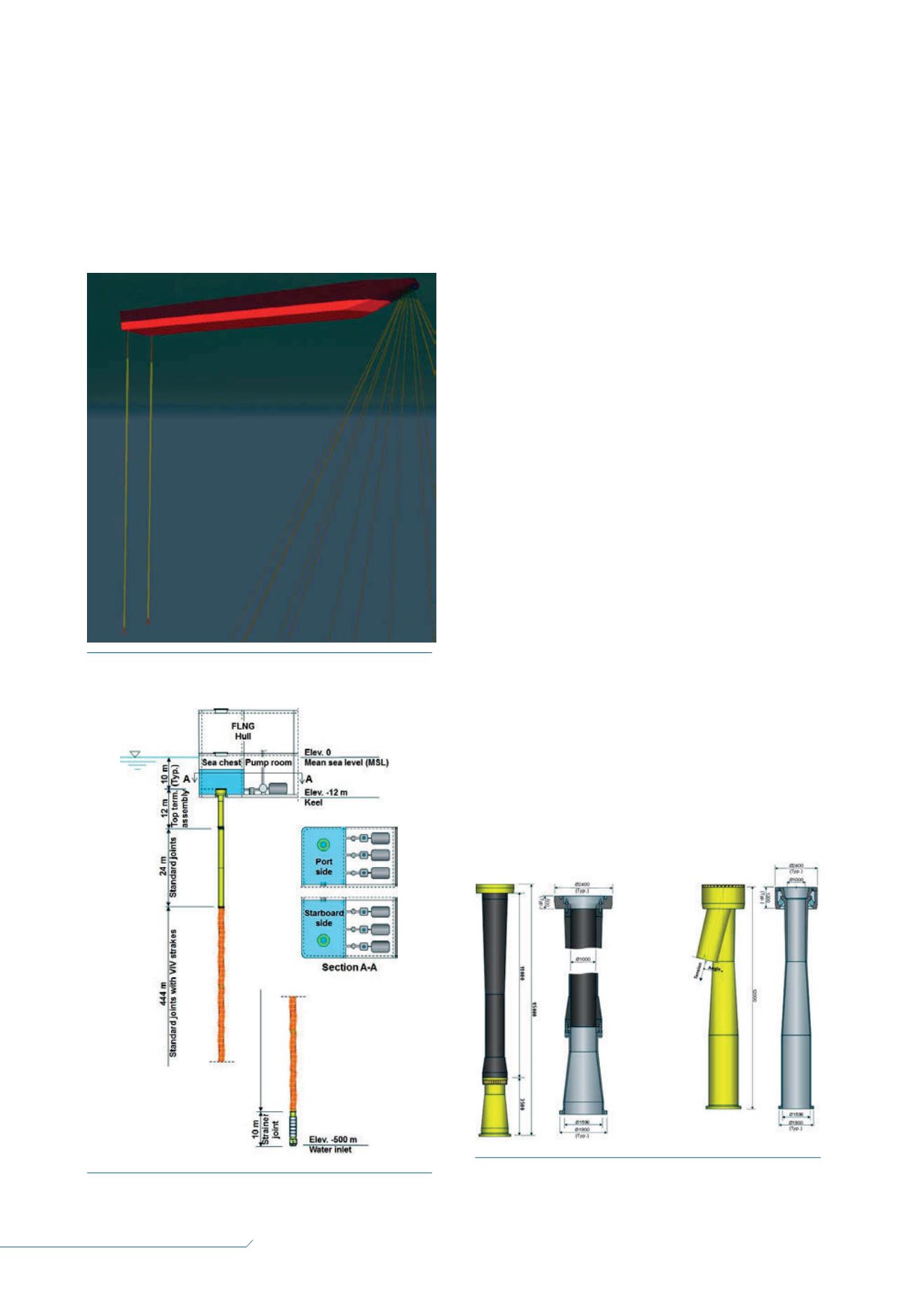
Figure 2.
Aker Solutions’ FLNG water intake concept for
fetching 35 000 m
3
/hr of seawater from 500 m water depth.
Figure 3.
Alternative flexible hang-off assemblies with locally
reduced diameter. Reinforced flexible hose (left) and flexible
bearing element (right).


