42
LNG
INDUSTRY
SEPTEMBER
2016
Design verification
An FLNG unit can seem to have a simple shape, being
based on a conventional ship-shaped hull. However,
due to its different operating mode, the FLNG unit is
much more complicated than a conventional carrier.
It is permanently installed in open water, leaving it
susceptible to extreme weather conditions. Process
equipment on deck is exposed to environmental damage,
which can have potentially catastrophic consequences.
The vessel will often weathervane around a turret in order
to face in a favourable direction to the weather, and so
the turret must resist all of the mooring loads, becoming
a key mechanical component in design and a major cost
driver.
It is not possible to reliably estimate all of these
design issues by calculation or computer simulation
alone. Therefore, physical model testing is an important
aspect of FLNG design. It is used during the concept
phase to verify the effectiveness of the hull form or the
selected turret location, and during the detailed design
phase to help resolve issues such as the anticipated
bearing loads on the turret caused by the FLNG motions
and the dynamic mooring loads. Certification authorities
and the International Maritime Organization (IMO) have
prescriptive rules to estimate wind forces and heeling
moments, but do not take into account the complex
interaction of different structures on the deck of the
FLNG unit.
Key features of wind tunnel
testing
Wind tunnel tests can be useful in providing a more
accurate estimate of wind forces and wind heeling
moments acting on the hull and topsides of an FLNG
unit. This forms a vital input into a stability analysis of the
FLNG unit itself, as well as an analysis of the mooring and
thruster systems.
It is important that the wind tunnel testing procedure
includes the following key features:
Six component force transducers for measuring steady
state wind forces and moments.
Two component hot wire anemometry for measuring
mean and turbulent flows.
A system for simulating, at model scale, the hot gas
flows from the various exhausts and measuring mean
and peak temperature at designated locations.
A system for simulating, at model scale, prescribed
gas releases and fire scenarios, and measuring mean
and peak local gas and smoke concentration at
designated locations.
From the general arrangement drawings, a 3D
computer-aided design (CAD) solid model can be created.
This model includes a detailed representation of the
topside modules as appropriate, in order to ensure that
the aerodynamic characteristics of the wind tunnel model
are as close a match as possible to those at full scale. A
rigid force balance model of the FLNG unit, suitable for
boundary layer force balance testing, is then created using
computer numerical control precision machining
techniques for the hull. The topside modules are then
produced using state-of-the-art rapid prototyping
techniques driven from the 3D CAD model, allowing for a
highly accurate representation of the topside modules in
accordance with the requirements of the specification.
The role of computational
fluid dynamics (CFD)
It is crucial that the CAD model includes a detailed
representation of all major equipment (e.g.
pumps, wellheads, vessels, etc.), the main
and secondary structural members, solid
barriers and buildings (e.g. blast walls,
local equipment rooms, etc.), as well
as small scale items, such as pipework,
handrails, grated decks, etc. The inclusion
or absence of each of these elements
can have an impact on key results. Once
a CAD model has been completed, a
computational mesh defining the FLNG
unit and the surrounding volume can
be created. The computational mesh is
created by discretising the surface of the
FLNG unit and the surrounding volume into
a number of discrete locations. At each
location, the equations governing fluid flow
are iteratively solved to obtain a solution.
Preliminary computational fluid dynamics
(CFD) solutions should then be obtained
for a range of significantly different
computational grid resolutions. Failure
to do so is a common cause of erroneous
results in CFD calculations and is a critical
step to ensure that the results obtained
from the analysis will be independent
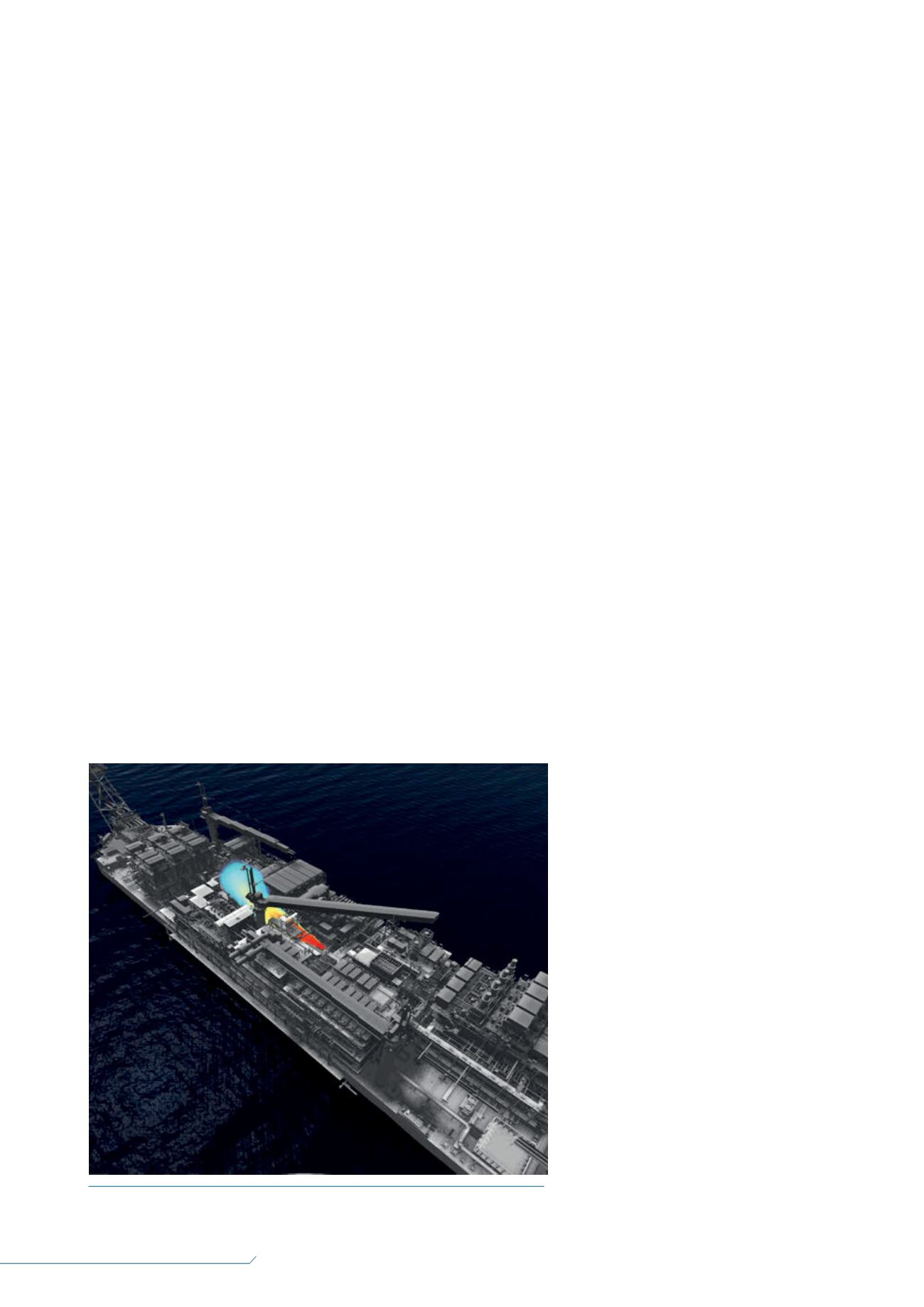
Figure 1.
Gas dispersion modelling using computational fluid dynamics (CFD).


