44
LNG
INDUSTRY
SEPTEMBER
2016
of the mesh resolution and within the accepted error
boundaries of the study being carried out.
Another important consideration in any CFD study
involving turbulent flows is the turbulence model used. A
number of different models exist, each with their own
range of applicability and, in most cases, it is not known
beforehand which turbulence model will offer the highest
degree of accuracy. However, through validation studies,
recommendations can be put forward as to the most
appropriate.
FLNG hazards
The most dangerous hazards associated with FLNG units
are those associated with the loss of containment of
hydrocarbon products and their subsequent ignition. As
demand for global energy drives the industry into more
inhospitable fields, deeper waters, high pressure reserves
and more sour streams, an understanding of these risks
becomes even more crucial to the safe design of the asset.
CFD is an ideal tool for assessing these risks and can be
applied to a variety of scenarios.
Loss of containment and the subsequent dispersion of
fluids is a potential source of risk for FLNG units. These
scenarios can include leaks from pressurised tanks,
pipelines, processing equipment and wellheads, which can
result in the dispersion of toxic gases or liquids into the
atmosphere and the formation of flammable gas clouds. A
key output of CFD analyses is typically the size of the
dispersed flammable and toxic gas clouds. This
information can then be used to inform the heating,
ventilation and air conditioning (HVAC) strategies and the
location of escape routes for personnel. It can also be used
to assess the impact to helicopter operations, locate gas
detectors and review design compliance with associated
regulations.
Fires pose a direct hazard to structures and personnel
due to the high temperatures and heat released from the
combustion process, as well as the smoke and dispersion
of toxic combustion products. Furthermore, large scale
fires, such as in the case of an oil spill pool fire, release
large quantities of toxic smoke. CFD analysis can,
therefore, be used for purposeful combustion processes,
such as flaring, where the impact to equipment and
personnel from thermal radiation needs to be controlled
through tower design and mitigating water sprays.
The evaluation of the blast loads on safety critical
elements (SCEs), such as hydrocarbon containment,
escape routes and overpressure protection, is an important
part of ensuring the structural integrity of those elements
and the FLNG unit as a whole. Blast loads typically result
from the ignition of flammable gas clouds caused by loss
of containment events. It is common practice in the
industry to apply regulations and industry standards, such
as the UKOAA Fire and Explosion Guidance or
NORSOK Z-013, together with the results from CFD
simulations to quantify these blast loads. These
simulations can provide time histories of overpressure,
impulse and drag, which can be used to calculate peak
values for both large surfaces and small scale items, such
as pipework. Subsequently, mitigation measures to help
reduce any adverse blast loads can then be investigated
and verified through additional CFD simulations. Measures
could include changes to the FLNG layout if design
constraints permit.
In order to quantify the level of risk to individual SCEs
and the FLNG unit, an exceedance analysis can be carried
out by combining the results of CFD fire, gas dispersion
and explosion scenarios with the corresponding frequency
for a given event. Given the complexity of the processes
on FLNG units and external factors, the number of possible
scenarios is infinite. As a result, this matrix is reduced to a
more manageable number. However, a significant number
of scenarios are still required to ensure that the levels of
risk calculated are not overly conservative. The impact of
each of these scenarios on individual locations can then be
brought together to generate a probability exceedance
curve. The curve is a measure of the likely frequency of a
scenario that results in a given consequence (e.g.
overpressure, impulse, drag, temperature, etc.). Design
parameters at a threshold frequency that represents an
acceptable level of risk to personnel and the FLNG unit can
then be determined.
Reducing design
conservatism
CFD, along with physical wind tunnel
testing, represent two different
approaches in the practice of fluid
dynamics. When carried out effectively,
they can help to considerably reduce
conservatism in design. Wind tunnel
testing can determine the wind and
current loads acting on the FLNG
topsides and hull, and provide important
input into stability, mooring and thruster
design, whereas CFD can highlight
important issues around the loss of
containment of hydrocarbons and their
subsequent potential ignition. Both
approaches represent inputs that are
critical to the safe design of an FLNG
unit.
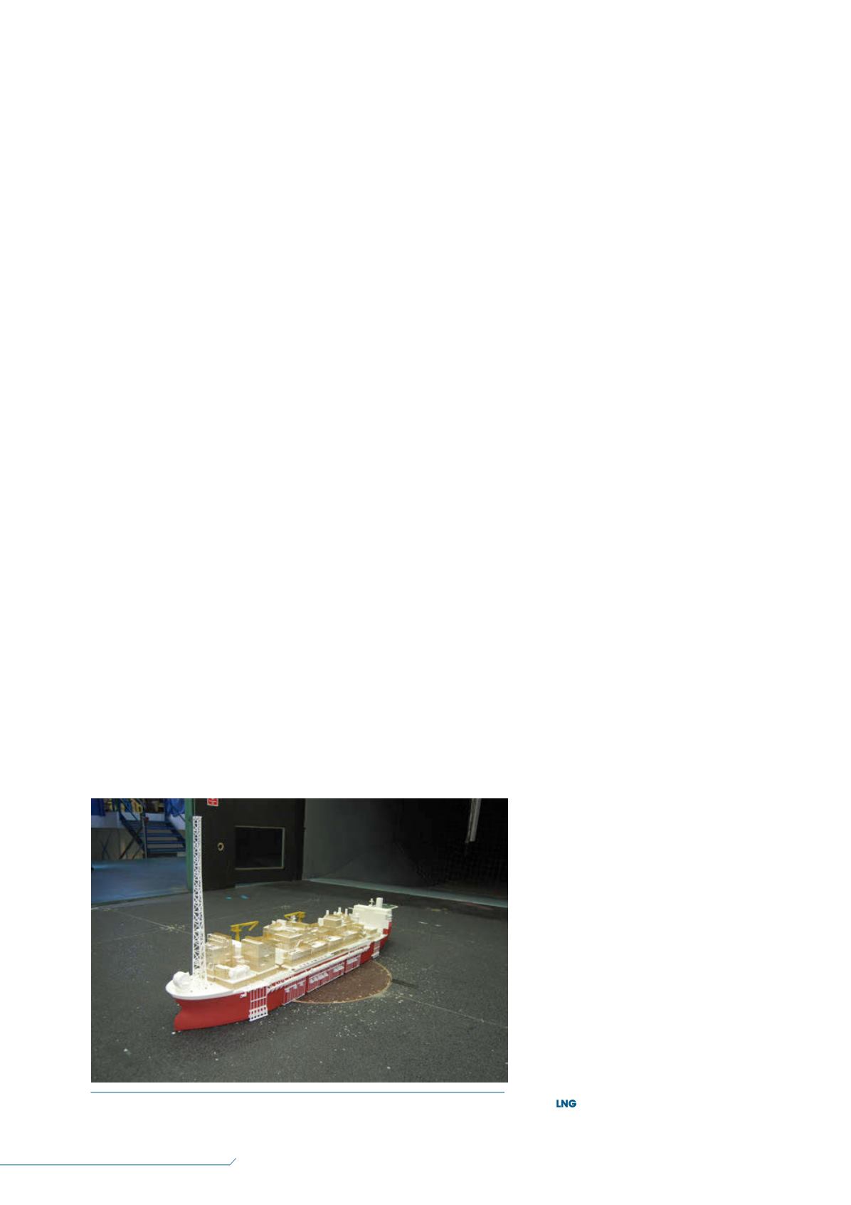
Figure 2.
Scale wind tunnel model.


