40
LNG
INDUSTRY
APRIL
2016
captive rectifier/harmonic filter transformer powering each of the
three large compressor strings in each unit. Each compressor
string is powered by a synchronous motor drive through a variable
frequency drive (VFD) that is connected to the captive
rectifier/harmonic filter transformer. These drivemotors are
controlled and protected by the VFD. Additionally, within each
LNG train, two 138 kV feeders serve the primaries of two
138 – 13.8 kV power transformers that will supply 4.16 kV, 480 V,
and 120/208 V stepdown power transformers. In general, these
transformers are arranged in double-ended, main-tie-main
arrangements to serve all of the remaining loads.
Diesel generators and uninterrupted power supplies (UPS)
featuring battery backup are provided within each LNG train for
essential loads.
Plot plan of an E-LNG plant
When compared to a conventional, same capacity, gas turbine
driven compressor train, the all-electric train requires a larger plot
space, primarily due to the ancillary equipment that the electrical
motors require.
Figure 1 is a snapshot of the 3Dmodel showing the three
compressor strings: (from left to right) the propane compressor
(shown without noise enclosure; note that all compressors and
motors are located inside off-skid enclosures that are installed on
top of the concrete compressor table tops), high pressure/
mediumpressureMR compressor (shown without shed) and the
low pressureMR compressor. Table 2 shows major electrical
components and its approximate plot area.
It is recommended to procure capital spares, such as a
completemotor (stator and rotor) as well as a VFD
rectifier/transformer and one set of VFD harmonic filter legs,
which are long lead items. Due to the large size and weight of
these components, a detailedmaintenance plan needs to be
developed to ensure that there is sufficient space to bring in large
cranes, as well as to ensure that the roads and warehouse are
designed to receive this heavy equipment. Table 3 shows the
approximate dimensions and weight of major electrical
components.
Availability/flexibility
As shown in Table 1, electric motor drives and aeroderivative gas
turbines providemore available days compared to industrial gas
turbines.
Aeroderivative gas turbines need inspection and servicing
every six months, major maintenance every three years and an
engine swap every six years. Engine swaps require the plant
owner to purchase a set of extra gas turbine enginemodules
equivalent to one LNG train. Frequent inspections cause frequent
shutdown of the gas turbine and coupled compressors. Engine
swaps require removing the engine from the plant for an overhaul
and, typically, offsite or onsite storage, which are all major
undertakings.
Electric motors are designed to run for three years without
interruption. It is possible to build redundancy within the
electronics in-drive system to extendmean time between failures
of the drive systemup to two to three years or even longer.
Freeport LNG’s concept of threemotors per train also
separates control of two refrigeration loop compressors fromeach
other, which simplifies overall liquefaction operation control. The
propane refrigeration compressor rotating speed can be adjusted
without directly affecting theMR compressors, since they are not
coupled to the same driver. A typical LNG plant with industrial gas
turbines has two compressor casings coupled to one gas turbine
and any rotating speed adjustment of one compressor affects all
of the connected compressors.
Electric motor drive selection for Freeport LNGwill increase
uptime and provide an opportunity for simplified operation
control.
Table 3.
Dimensions and weight of the main electrical
components
Item
Dimensions: length
x width x height (m)
Weight (t)
75 MW electrical
motor
10 x 6 x 7.3
245
75 MW VFD
16.4 x 10.4 x 2.7
37
138 kVA transformer 8.9 x 6 x 7.4
95 (transport weight
– without oil)
Table 2.
Plot area requirements for major electrical systems
Item (see Figure 1) Description
Plot area (m
2
)
1
138 kV transformer
105
2
E-house building
(compressor VFD, low
voltage motor control
centre (MCC), unit control
panel (UCP) system,
fire and gas (F&G) for
compressor and motor
enclosure)
550
3
Compressor and motor
550
4
VFD cooling package
450
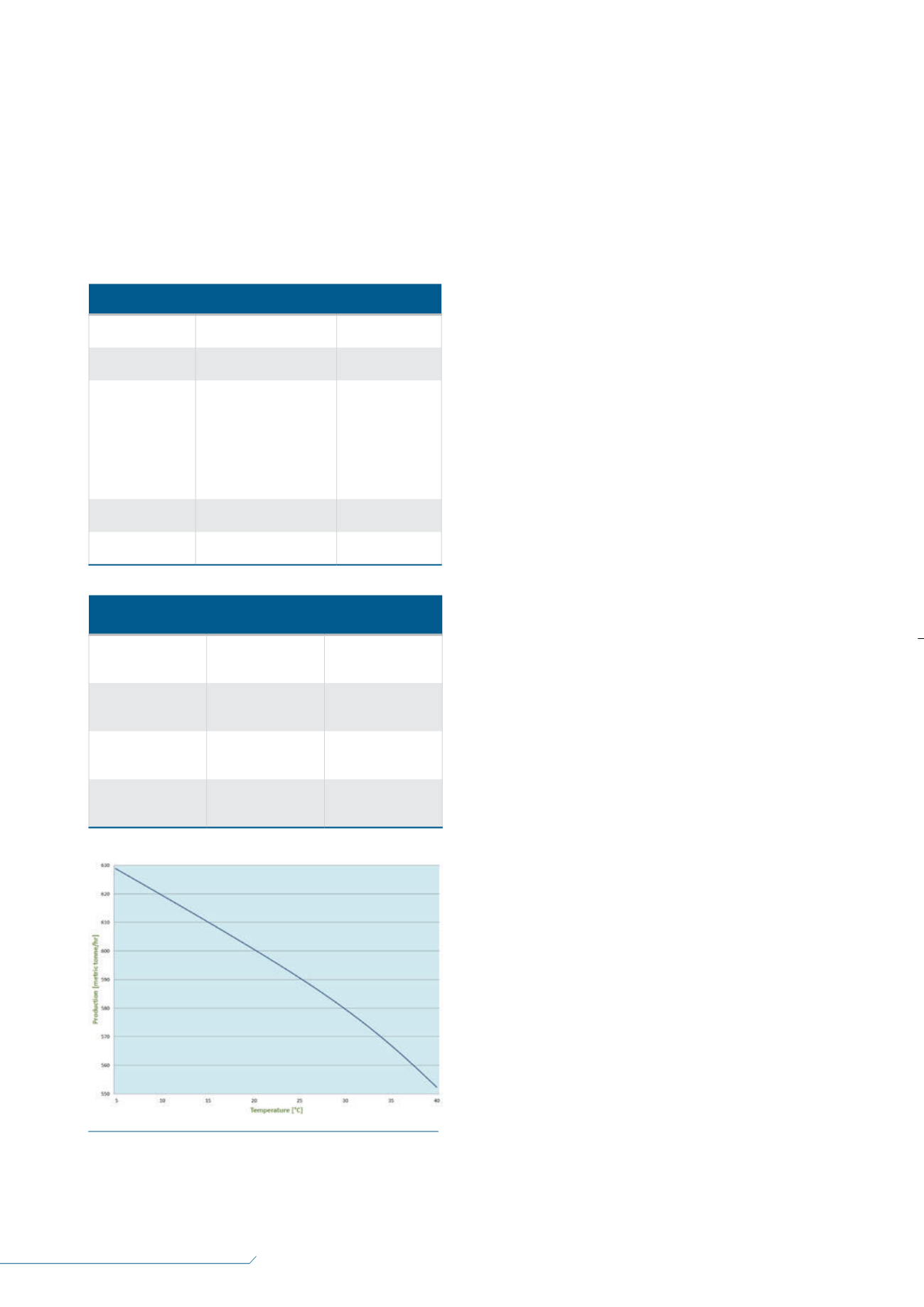
Figure 2.
Estimated production profile for all-electric
refrigeration cycles (air cooled liquefaction plant).


