For typical BOG sources and indicative flows for a floating
storage and regasification unit (FSRU), refer to Table 1.
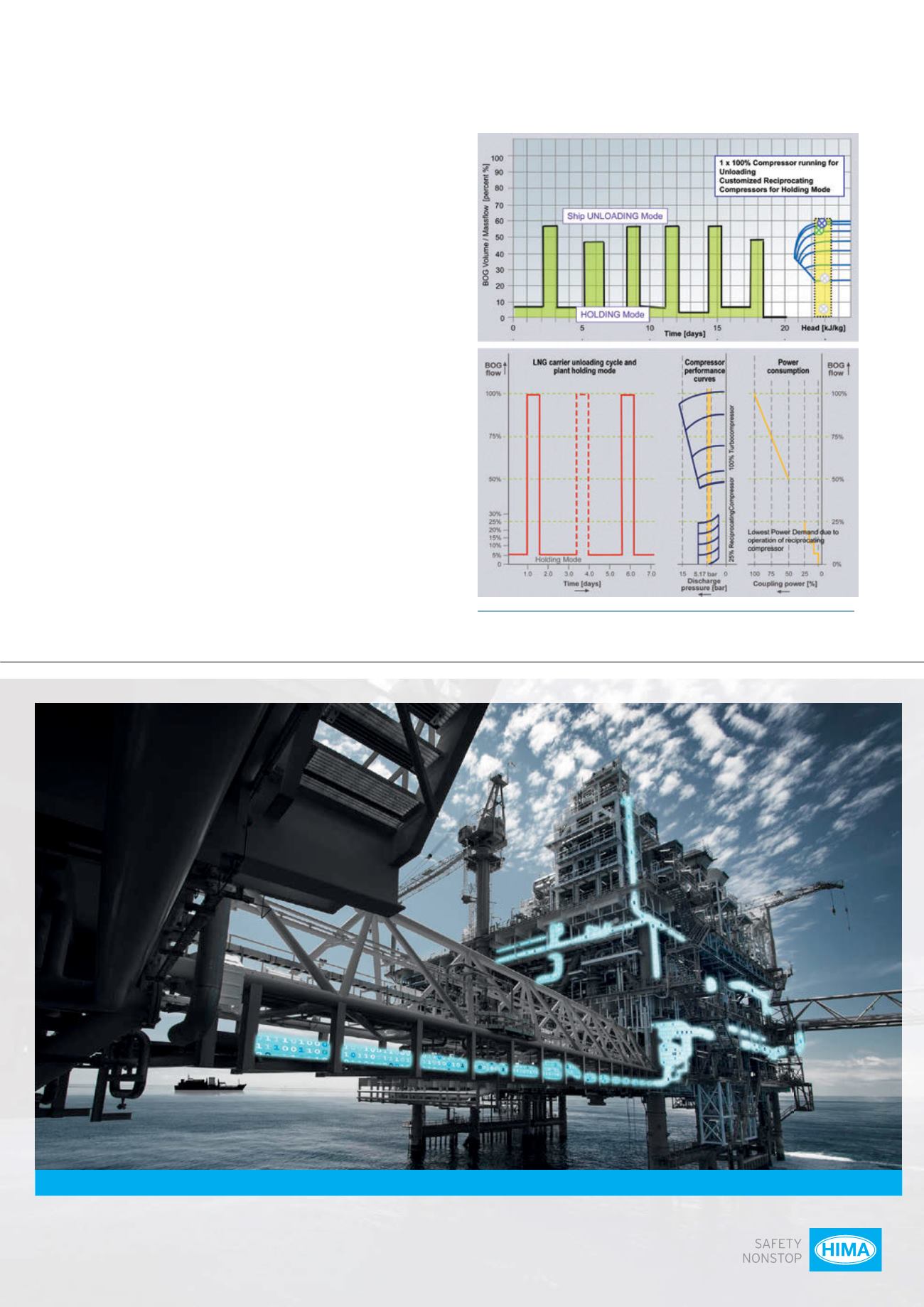
The relatively high maximumBOG flow and the difference in
BOG volume fluctuations between holding and ship unloading
require a combined compressor concept. In Figure 4, the spread
ranges from 32 tph down to 2 tph, which can only be handled by
combining both the strength of the single-shaft turbocompressor
and reciprocating machines.
While the loading requirements are handled by one 100%
turbocompressor package, the small holding operating points are
operated by either existing terminal extensions, or new
reciprocating compressor packages.
With the configuration outlined in Figure 4, optimised
compressor BOG handling concepts become increasingly attractive.
Rather than covering the whole BOG flow range by small LNG
re-liquefaction units (single-cycle N
2
LNG cooling), or multiple large
reciprocating compressors (re-condensing concept), it is more
energy efficient to cover the maximumBOG duty through a
single-casing, single-shaft centrifugal compressor combined with
reciprocating machines.
In summary, of the outlined concept descriptions and based on
the factors of maximumBOG flow and minimumBOG flow, the
following compressor concepts (visually portrayed in Figure 5) for
BOG handling can be used:
Concept A (conventional arrangement for LNG receiving
terminals):
2 x 50% (plus one spare) or 3 x 33% reciprocating
compressor.
Figure 4.
Simplified BOG generation and operation profile (LNG
import terminal), combining turbo and reciprocating compressors.
ESD
F&G
HIPPS
Subsea
Pipeline
TMC BMS
Comprehensive
Safety Solutions
increase Profitability
Visit us at OTC in Houston: Hall B, Booth 4527-17


