50
LNG
INDUSTRY
APRIL
2016
Unloading: all 2/3 compressor units run in parallel.
Holding: one unit runs under bypass control.
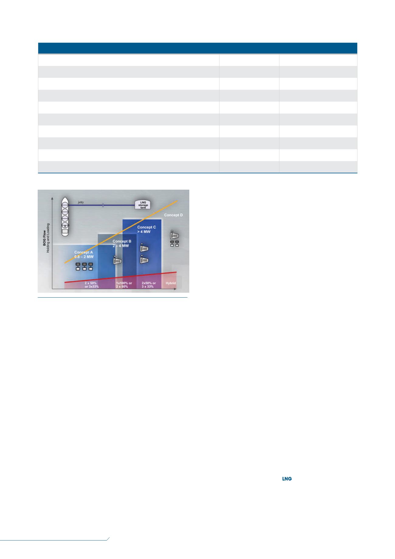
Concept B (most commonly used):
1 x 100% (no spare unit) or 2 x 50% single-casing,
single-shaft centrifugal compressor.
Unloading: compressor unit runs at high IGV setting.
Holding: compressor unit runs at a minimum IGV setting
in automatic start/stop frequency, leading to the most
economic plant operation.
Special note: for offshore installations, such as an LNG
carrier converted into an FSRU, the holding BOG flow
is used to fuel the steam boilers for the onboard steam
turbine driven power generators.
Concept C:
2 x 50% or 3 x 33% single-shaft centrifugal compressor
packages.
Unloading: compressor units run in parallel at high IGV
settings.
Holding: one compressor unit runs at different low IGV
settings.
Concept D (hybrid):
1 x 100% (ship unloading compressor) single-casing,
single-shaft centrifugal compressor running with high
IGV setting during ship unloading, plus two small
customised reciprocating compressors covering the
holding mode
Unloading: single-shaft centrifugal compressor runs at
high IGV setting only during LNG tanker unloading.
Holding: small customised reciprocating compressor runs.
It is important to understand that the optimised BOG
recovery concepts for LNG import terminals require
compressors that are capable of direct online start/stop
operation in order to avoid compressor cool-down with
associated gas flaring, as well as utilising reciprocating
compressors suitable for cryogenic gas applications.
Key design features for this achievement are the
turbo-type compressor design, material selection and
combination for cryogenic service, dry gas seals encapsulated
in heated seal carriers, and an adjustable IGV compressor
control system.
Single-body, single-shaft BOG centrifugal compressors are
customised for exactly this purpose, as they are specifically
designed and engineered for maintenance-free, intermittent
(start/stop) operation from ambient, as well as from cold
conditions, without any special cool-down procedures.
These unique features make the units the best technical and
most reliable fit, and provide the highest possible start-up
availability customised for the needs of today’s state-of-the-art
LNG import and export terminals.
Conclusion
The demand for safe, efficient and cost-effective compression
systems for handling BOG on both carriers and LNG receiving
terminals is greater than ever before. This means that
maximum BOG flows are increasing and require a custom
engineered compressor solution (or configuration).
This scenario uses the advantage of cold gas reciprocating
compressors for low-flow handling and turbocompressors for
higher loads, which goes beyond the application range of
reciprocating BOG compressors.
Reference
1. ‘World LNG Report 2015 Edition’, International Gas Union,
/
IGU-World%20LNG%20Report-2015%20Edition.pdf
Figure 5.
The application range of different compressor types
in receiving terminals.
Table 1.
BOG sources – a typical case study
Source of BOG
Unloading mode (kg/hr)
Holding mode (kg/hr)
Flash due to ship cargo tanks operating at higher pressure than onshore LNG tanks
3600
–
Pumping heat from unloading pump
20 000
–
Unloading line heat leak (with 20% added for fittings, expansion loops, etc.)
1700
–
LNG tanker (ship) cargo tank heat leak
6000
–
Onshore LNG tanks heat leak
2000
2000
Vapour return to ship cargo tanks
(22 000)
–
Negative displacement due to LNG sendout
(1300 variable)
(1300 variable)
Displacement from LNG tanks due to unloaded LNG
22 000
–
Total
32 000
2000 maximum. Down to zero


