


 36 / 60

34
April 2020
the multiplication of the reliability of each component. Since
there are many components, the reliability can be estimated
using the reliability of some key modules such as the diode
assemblies, power module assemblies, etc. The reliability of
the VFD will be less than the reliability of the least reliable
module:
Where ‘R
VFD
’ is the reliability of the VFD, and ‘R
M
’ is the
reliability of each module. For example:
Other than intrinsic reliability, redundancy can be built in
many configurations with the increased number of
components. One form of creating redundancy is installing
duplicate systems in parallel, known as hot redundant
systems. In this configuration, the components or modules
operate all the time, sharing the load. When a path fails, other
paths continue to operate, ensuring power delivery. Only when
all paths fail will the entire system fail. Because the parallel
circuits run at the same time and share the load, they age
equally and can be affected by large technical failures.
When the failing rates of each chosen module (F
M
) have
been accounted for and recorded, the reliability of the VFD
can be estimated using:
Where ‘n’ is the number of modules under consideration, ‘t’
is the time of operation and ‘F’ is the probability of failure.
But, since failure rate can be expressed as Fi(t) = 1– Ri(t),
where ‘F’ represents the probability of failure of the ‘i
th
’
module, and ‘Ri’ represents the reliability of ‘i
th
’ module, the
reliability can also be calculated using:
There are other configurations of circuits or components
in use in VFDs to create redundancy, as well as many
combinations of redundancy methods, all of which add more
components and complexity to the equipment.
When standby modules, circuits or components exist, the
reliability can be calculated as:
Where ‘n’ represents the number of standby modules or
circuits or components, ‘t’ represents time, and ‘
λ
’ represents
the failure rate. When only one standby module, circuit or
component exists, the expression becomes:
The same expression can be used when a whole VFD is
used to standby for many other equal VFDs in a production
facility, or the operation employing one VFD is supercritical.
VFDs are maintainable and, in most cases, preventive
maintenance is economically viable and highly preferable over
corrective maintenance. To plan for maintenance works, the
uptime availability of the VFD can be used.
The uptime or steady-state availability is defined by:
Where ‘A’ is the availability of the VFD, MTBF means
mean time between failure, and MTTR means
mean time to repair exclusively dedicated to the repair. In
other words, excluding, for example, waiting times for parts,
tools and setup time. Figure 6 highlights steps accounted for
as MTTR.
Over time, the availability of a VFD can be retained
through weekly-monthly inspections observing the following:
z
Changes in the installation environment, such as
temperatures, appearances of dust, humidity and gases.
z
Abnormal sounds or vibration in the transformer, or
cooling fans.
z
Unusual smells of insulating substances, peculiar to
electric circuits failure.
In addition to regular inspections focusing on:
z
Maintaining the interior of the cubicle and keeping the air
filters clean.
z
Looking for part discoloration, deformation, leakages of
components, circuit boards and wiring.
Identification of fault on
VFD panel
Repair or set up
Removal of
faulty part
Installation of
new part
Preparation for
operation
Turn supply
power on
Checks before
powering
Closing doors
Figure 6.
High-level repair process.
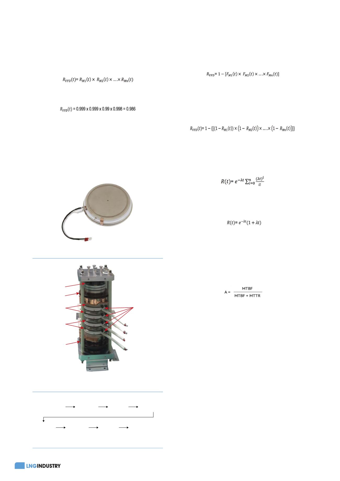
Press Pack
IEGT
Spring
Insulator
Cooling Heat
Sink
Insulator
Cooling Heat
Sink
Figure 5.
Example of a PPI assembly (stack).
Figure 4.
Injection enhanced gate transistor (IEGT).7