70
LNG
INDUSTRY
JULY
2016
boxes can be loaded on and under deck). In this article, only the
geometric counting method will be used.
For a given commercial trade, the vessel speed is a function
of the weekly sailing (time interval between two calls of the
vessels from a given commercial service) vs the number of
vessels on the trade. Depending on arbitration between market
needs and other parameters, such as OPEX (including bunker fuel
costs), the commercial vessel speed might be adapted from
approximately 10 knots to more than 20 knots. As a result, the
propulsion must be optimised for a wide range of speeds.
Reference ship
As references for this study, two designs of 19 000 TEU class
container vessels were retained: one running on HFO, and
another running on natural gas.
The following are the most relevant design parameters used
for this study:
Length overall (LOA): 400m.
Beam: 59 m.
Depth: 30.2 m.
Container capacity: approximately 19 000 TEU (11 tiers on
deck; 11 tiers in hold).
Single screw layout, shaft line driven by a two-stroke diesel
engine without gearbox.
Propulsive power: 65 MW.
Design speed: 22 knots at scantling draft.
The aim of this study is to compare the different layouts of
diesel, dual-fuel and COGAS propulsion. The COGAS concept
strictly sticks to reference designs. Only the propulsion driver and
power generation plant are changed.
General description
As mentioned previously, the following two axes drive this
concept: increase the cargo capacity and decrease the ship’s
OPEX.
To achieve these goals, Marine Assistance and GTT decided
to investigate further in the following directions:
Replace the large and heavy two-stroke piston engines
(direct mechanical drive) with slow speed, in-line electric
motors powered by a power plant consisting of several gas
and steam turbines.
Use an electric propulsion system to remove the funnel
casing and replace it with container tiers.
Use membrane type tanks to bunker LNG.
Adopt a new layout with electric production and LNG tanks at
midship and electric propulsion aft.
The most interesting principle about electrically propelled
ships is to dissociate power generation from power consumption.
This provides a lot of flexibility and additional freedom for the
ship designer on the general arrangement of the vessel.
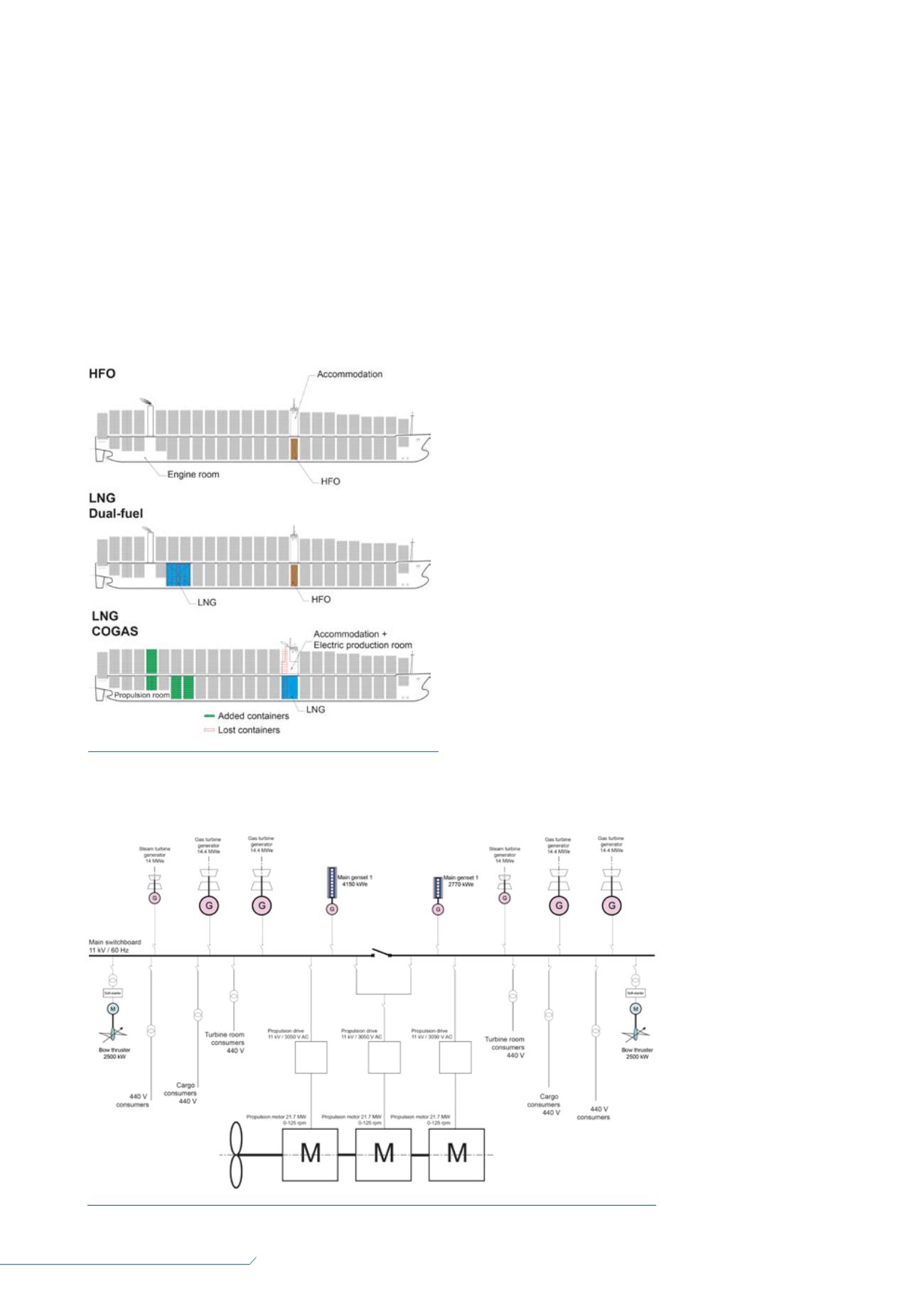
As can be seen in
Figure 1, the power
generation and the LNG
tanks are located below the
accommodation block in a
volume that cannot be used
for the cargo. At the aft of
the container carrier, a small
propulsion room replaces
the engine room, while the
funnel is suppressed,
enabling the vessel to carry
more containers.
LNG bunker
tanks
For a given volume of
bunker tanks, the amount of
energy contained in LNG is
only 60%of that contained
in HFO.
The consequence for an
LNG-fuelled vessel is
Figure 1.
Schematic layout of the combined gas electric
and steam (COGAS) concept vs diesel and dual-fuel reference
vessels (
©
Marine Assistance).
Figure 2.
COGAS preliminary electrical single line diagram (
©
Marine Assistance).


