72
LNG
INDUSTRY
JULY
2016
reduced fuel endurance, which will force the ship to bunker more
and perhaps lose time andmoney if LNG bunker operations cannot
be carried out simultaneously with cargo operations.
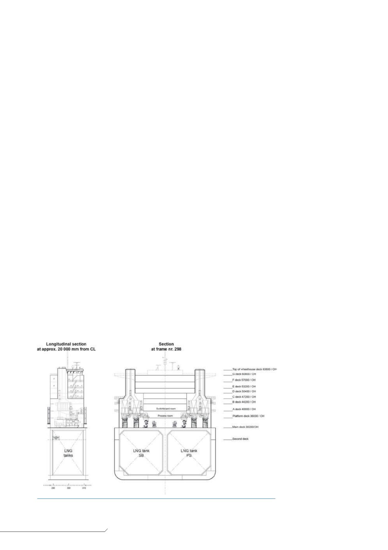
To grant the same fuel endurance, it has been decided to
provide the ship with the same energy equivalent storage as the
conventional vessel. Therefore, twomembrane tanks – each with a
geometric capacity of 10 960m
3
– are installed for LNG storage.
The LNG containment systemwas designed by GTT with
Mark III Flex membrane technology. The LNG tanks were specially
designed for high thermal performance and safe operations under
all filling levels, whatever the sea state.
The tank pressure safety valves are set at 0.7 barg as per the
International Maritime Organization’s (IMO) IGF code for the design
and building of LNG-fuelled vessels. At a later stage of this study,
the scantling of the ship structure will be reviewed to allow for
higher pressure in LNG tanks if needed, as this could facilitate
bunkering operations and boil-off management.
Electric plant design
Design principle
The total power demand of a container carrier depends on its
activity. For instance, the power demand is relatively low at quay
(only reefer containers and hotel loads must be satisfied), but is
much higher when the container carrier is travelling full speed at sea
due to the necessary propulsive power. With the COGAS concept,
all power consumers are electrically driven, including propulsion.
Therefore, only the electrical demand was considered in the study.
To design a suitable and efficient power plant, threemain
principles were retained:
Segregation of the power plant: to achieve the best efficiency,
the power plant capacity must be well adapted to the power
requirement. For this reason, the power plant capacity is
split into eight different generators that can be activated
automatically upon request by the Power Management System
(PMS).
Standardisation of the power plant: having identical power
generators leads to easier crew training and cheaper
maintenance. For this reason, the power plant is made of only
three different generator models: one gas turbine, one steam
turbine and one dual-fuel genset.
Off-the-shelf equipment: for this project, only sea-proven,
‘off-the-shelf’ equipment fromSiemens (for gas and steam
turbine generators), Wärtsilä (for dual-fuel gensets) and ABB
(for electric propulsion, automation and instrumentation) was
used.
Power plant layout
Based upon previous principles, the power plant is composed of
the following:
4 x Siemens SGT 400 gas turbine generators, rated each at
14.4MWe.
2 x Siemens/Peter Brotherhood steam turbine generators, each
rated at 14MWe.
2 xWärtisilä dual-fuel gensets, 6 L36 (2.8MWe) and 9L36
(4.15MWe).
Figure 2 gives a preliminary electrical single line diagramof the
COGAS container vessel, while Figure 3 shows the preliminary
arrangement of the electric production room.
LNG system
The power output and efficiency of gas turbines depends on
atmospheric conditions and especially the temperature of the
combustion air. The lower the air combustion is, the higher the
power output and efficiency of the gas turbine.
Therefore, in order to provide the coldest possible combustion
air to the gas turbine, a thermal exchanger between the LNG
vaporiser and air intakes has been designed. Essentially, the
combustion air flow is used as a heating source to vaporise the
LNG. The process is achieved by means of a glycol/water loop used
as a heat carrying fluid.
While sailing, this device enhances gas turbine output by up to
13%. Overall, the COGAS electric plant efficiency can exceed 50%.
Figure 4 gives the principle scheme of the LNG fuel system.
Propulsion
The single shaft arrangement
is designed for 22 knots at
scantling draft. This requires
65MWat the propeller side.
During the study, different
propulsive layouts with or
without a gearbox have been
reviewed with ABB. Further to
this analysis, a configuration of
three electric synchronous
slow speedmotors has been
retained.
Compared to a
conventional two-stroke slow
speed diesel engine (or even a
dual-fuel two-stroke engine),
the electric propulsion offers a
more compact design and
does not require funnel casing.
The additional space is used to
carry extra containers.
Figure 3.
Extract of the electric production room plan (
©
Marine Assistance/Siemens).


