28
LNG
INDUSTRY
MARCH
2016
Investment in new fabrication facilities for the coil wound
exchangers used in the precooling cycle and as the main
liquefier has effectively removed previous limits.
Refrigerant compressors and drivers
Over five decades, the LNG industry has seen constant
innovation to increase capacity and improve efficiency, despite
a culture of risk aversion. The onshore LNG business has done
this through landmark projects.
The main step changes in capacity have come with the
introduction of new machinery, such as the following:
GE Frame 5 gas turbines in the 1980s led to the
abandonment of steam turbines.
The introduction of the GE Frame 7 in the early 1990s saw a
threefold increase in gas turbine shaft power.
10 years ago, the GE Frame 9 for the AP-X trains in Qatar
raised shaft power by another 50%.
New high power output marinised gas turbines are the key
to high capacity FLNG. Such machines should ideally also have
high availability, be lightweight and offer high efficiency,
although these may be secondary considerations. Several
manufacturers have new machinery solutions operating
onshore, sometimes in power generation service. Given the
LNG industry’s track record in qualifying new machinery, these
gas turbines are likely to be available for the next generation of
projects.
Layout
Process schemes and equipment selection need to be
reviewed again, with a view to identifying opportunities for
intensification.
Improvements in risk-based modelling results in more
efficient safeguards and mitigation measures. The use of blast
walls rather than, or in combination with, safety gaps needs to
be evaluated.
The use of wireless networks should also be promoted to
reduce layout footprint and topside weight.
A better understanding of operation and maintenance can
be used to define new approaches that can help reduce the size
of the living quarters.
Cooling
Indirect seawater cooling with a deep inlet riser to take
advantage of cold temperatures is a major advantage
compared to onshore LNG. It increases LNG capacity by
reducing the precooling refrigerant condensing temperature
and can optionally be used to cool the gas turbine inlet air
to increase the available power in warm weather and hence
production.
LNG handling
As LNG production is intensified, the ratio of storage to
production declines so that frequency of offloading to tankers
must increase. HiLoad LNG is one solution:
Connection and uninterrupted loading in sea states above
4 m wave height (H
s
).
Approximately 100 m separation distance at all times
between the LNG carrier and the FLNG facility.
Use of any LNG carrier without modification: connection to
the LNG carrier midship manifold without any load on the
flanges.
Control of LNG carrier heading and movement by HiLoad.
Proven components: Sevan HiLoad (references in oil
transfer) and Technip cryogenic flexible pipe.
Summary
Whatever solution is adopted, FLNG has an important
advantage over onshore LNG. It allows a more sustainable
development of offshore gas reserves by avoiding disruption to
sensitive and valuable coastal environments.
Replication will remain a key feature of FLNG, as it brings
schedule and cost certainty.
If the large capacity FLNG concept is developed, Technip
believes that its widespread replication and application will
follow. FLNG will thereby benefit from both routes – innovation
and replication.
References
1.
LNG17-proceedings/12-1-Barend_Pek.pdf
2.
/
scarborough_enviro_final.pdf
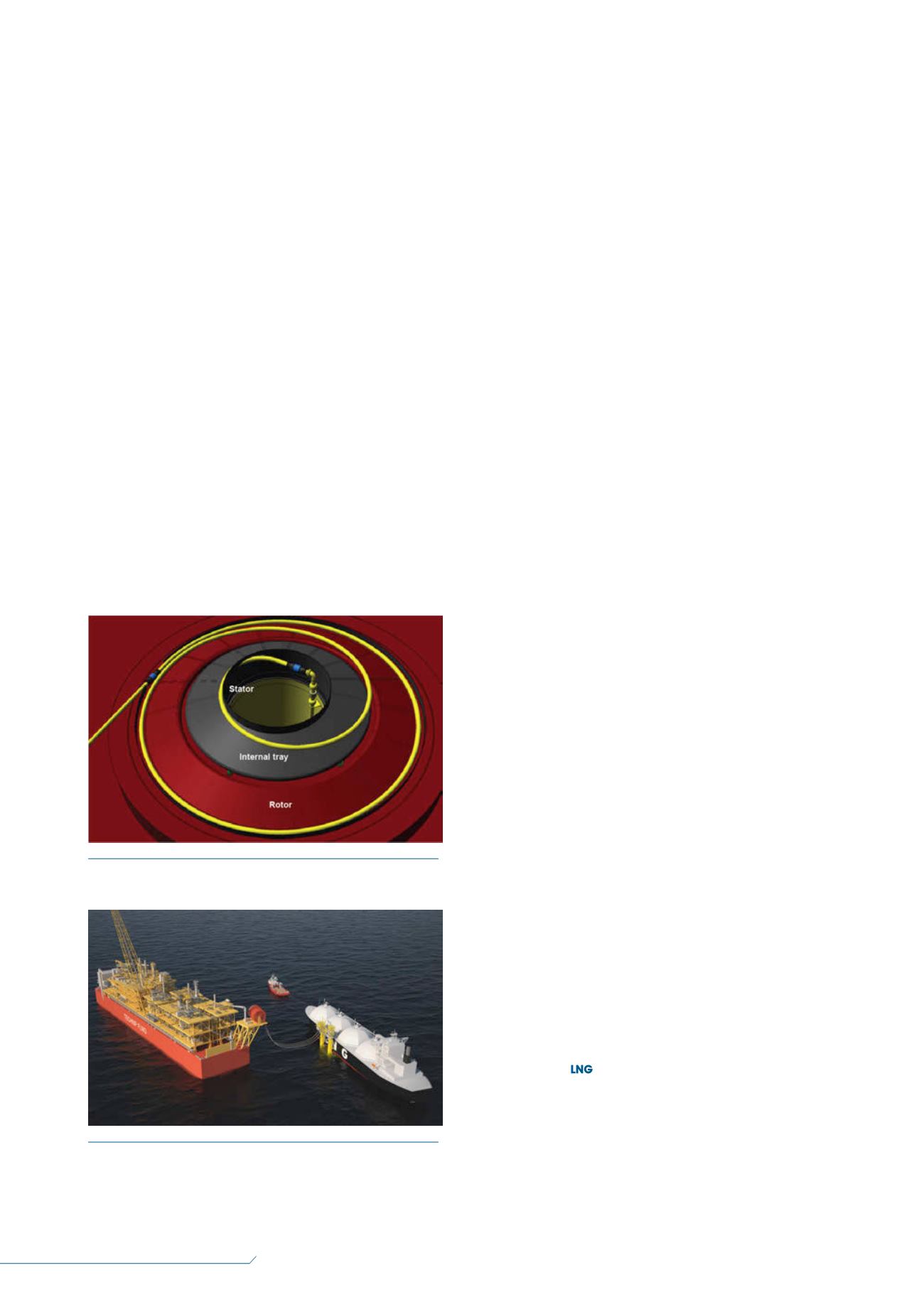
Figure 4.
Technip’s SST typical layout.
Figure 5.
The HiLoad LNG Parallel Loading System using
Technip’s ALLS cryogenic flexible flowlines.


