20
LNG
INDUSTRY
MARCH
2016
high pressure and heat is rejected into the atmosphere
through the compressor intercoolers and aftercooler.
The refrigerant is further cooled in the main cryogenic
heat exchanger (MCHE) and then expanded to cryogenic
temperature in a turboexpander. Once expanded, the
nitrogen enters the cold side of the MCHE, where it
precools, liquefies and subcools the feed, as well as
initially cools the warm nitrogen. After leaving the MCHE,
the low pressure refrigerant returns to the compressor
suction.
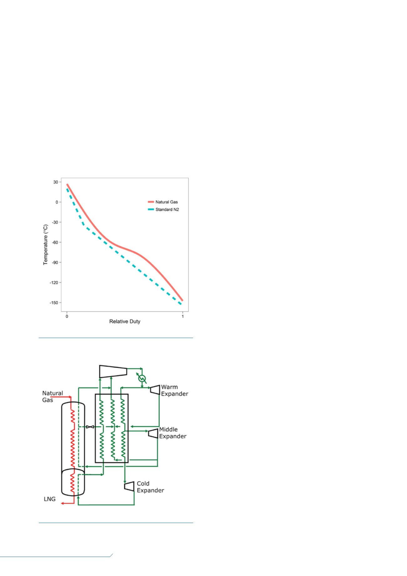
The cooling curves for this process are given in
Figure 3. In this figure, the hot side temperature, shown in
red, is the temperature of the natural gas feed as it is
precooled, liquefied and subcooled. The curvature in
temperature line is due to the latent heat removal from the
condensing mixture. The temperature profile for the
nitrogen, cold side, is straight without any curvature. This
is because warming of the cold nitrogen vapour is all
sensible heat as there is no phase change.
The bend in the nitrogen line is where the ‘hot side’
nitrogen exits the main exchanger and enters the
expander. Notice that the difference between these two
cooling curves changes through the exchanger. The larger
gaps show that there is underutilised refrigerant, which
translates to inefficiencies in the process or, conversely,
represents room for process improvements.
This standard process is simple with minimal
equipment. It is often used in small plants, such as peak
shavers where the production is only a few hundred tons
per day.
3
However, as this process is scaled up to
capacities relevant for FLNG, it becomes less simple, since
the expander duty will increase to the point where
multiple units in parallel will be needed, as well as their
associated piping. In addition, the number of brazed
aluminium heat exchangers will increase such that
multiple cold boxes and the associated piping will be
required.
Another factor to be considered is thermal stresses on
the heat exchange equipment. The cold side of the
exchanger will have cryogenic liquid and the hot side will
have cryogenic vapour. During upset conditions it will be
quite easy to get an imbalance in duty, creating large
thermal gradients in the exchanger because the refrigerant
flow is independent of the natural gas feed flow. The
likelihood of these gradients occurring also increases with
the size of the piping system and number of cores and
cold boxes in parallel. Coil wound heat exchangers have
years of operating experience, demonstrating that they
can withstand these stresses. In addition, the process tube
bundles in the coil wound heat exchanger are enclosed
within a pressure vessel shell, providing an additional
level of containment in the unlikely event of a leak due to
maloperation.
Case study
Two FLNG projects that are in construction,
Petronas FLNG
Satu
and Petronas FLNG
Dua
, will use the
AP-N liquefaction process.
For these large capacity liquefiers, the patented AP-N
liquefaction process
4
takes advantage of the multiple
expanders required and coil wound exchangers to improve
the robustness and efficiency of the process for FLNG
service. As shown in Figure 4, the natural gas, shown in
red, is liquefied in a coil wound exchanger. The gas is
precooled in the top section (often termed ‘bundle’),
liquefied in the middle section and, lastly, subcooled in
the bottom section. Those familiar with the use of coil
wound heat exchangers in land-based mixed refrigerant
(MR) cycle plants will notice that the coil wound heat
exchangers for the N2 cycle are ‘cold end down’ rather
than the typical ‘cold end up’ configuration. This is
because the refrigerant, being all vapour, does not need to
make use of gravity as in processes where the warmed
refrigerant condenses to a liquid. The nitrogen economiser,
which has nitrogen vapour on both the hot side and cold
side, can be brazed aluminium exchangers, since the fluids
Figure 3.
Cooling curves for standard nitrogen cycle.
Figure 4.
AP-N liquefaction process.


