22
LNG
INDUSTRY
MARCH
2016
are all gas phase and the hot and returning cold flow are
inherently balanced.
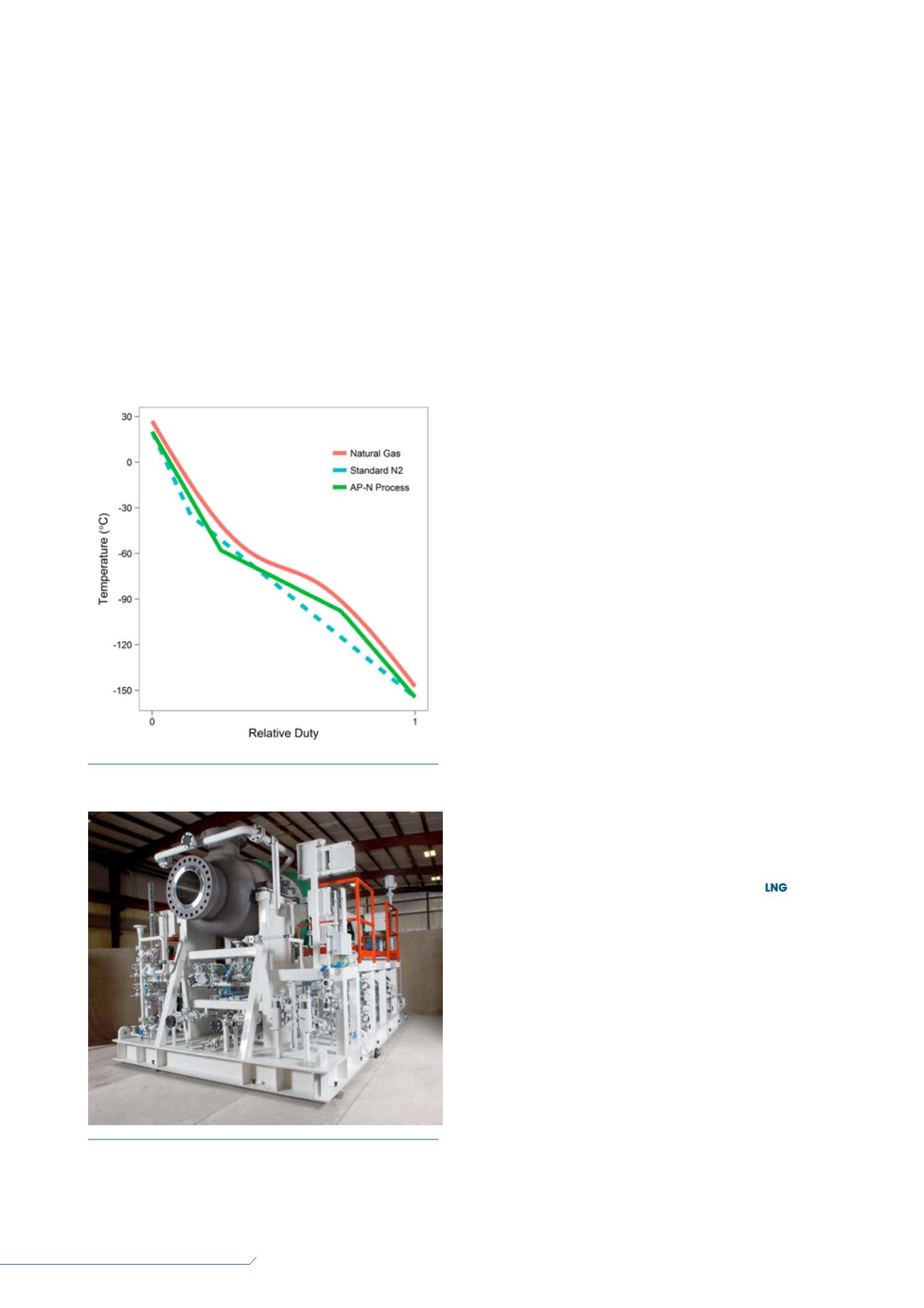
Instead of simply scaling up the standard nitrogen
process by placing the three expanders in parallel, they
are arranged to optimise the cooling curves for both the
liquefaction exchanger and the economiser exchangers.
The cooling curve for the AP-N liquefaction cycle is given
in Figure 5. The arrangement of the expanders allows for
two bends in the refrigerant cooling curve, such that this
refrigerant curve follows more closely with the feed
cooling curve, creating a more efficient process.
One expander is used on warm nitrogen to provide
precooling refrigeration and another larger expander is
used on colder nitrogen to provide the refrigeration for
the liquefaction. The third remains on the coldest
nitrogen to provide refrigeration for subcooling.
Turboexpanders
The expander arrangement in the AP-N liquefaction
process is such that each has a separate refrigeration
duty. Although not shown in Figure 5, the work generated
by the expanders is used to provide the final stage of
compression in a parallel compressor arrangement. This
arrangement requires that the expander-compressor
(compander, Figure 6) units work harmoniously together
while providing the individual adjustability to properly
balance and regulate the refrigeration for each service.
Therefore, the compander design team must work
closely with the process engineering team to ensure
that the companders will be able to provide the required
refrigeration and compression, as well as the operational
flexibility and durability required for all steady state and
transient operating conditions.
As with all shipboard equipment, there are challenges
and trade-offs with respect to weight, deck space,
maintainability, operability and reliability. The
Air Products compander design package utilises rugged
oil bearing technology and robust passive thrust
balancing systems to enhance reliability and limit
operational constraints for a compact, robust and
maintainable package.
Conclusion
There are additional challenges when designing an LNG
plant for floating applications. A number of liquefaction
processes are available (each with their own unique
features) to address these challenges. AP-SMR and
AP-DMR are efficient liquefaction processes that use
boiling hydrocarbon refrigerants. The AP-N liquefaction
process uses a non-flammable single-phase refrigerant
and the rotating machinery is highly integrated for
increased efficiency. One similar aspect of each of
these three processes is that the natural gas is liquefied
in a robust coil wound heat exchanger for safety and
reliability. All are suitable for floating plant service and
each has its own attributes, which project developers
may find attractive for their specific application.
References
1. BUKOWSKI, J. D., LIU, Y., PILLARELLA, M. R.,
BOCCELLA, S. J., and KENNINGTON, W. A.,
‘Natural gas liquefaction technology for floating
LNG facilities’, 16
th
International Conference and
Exhibition on Liquefied Natural Gas, Houston, Texas,
US, (2010).
2. BUKOWSKI, J. D., LIU, Y., PILLARELLA, M. R.,
BOCCELLA, S. J., and KENNINGTON, W. A., ‘Take to
the seas’,
LNG Industry
, (January/February 2014),
pp. 34 – 40.
3. BRONFENBRENNER, J. C., PILLARELLA, M. R.,
and SOLOMON, J., ‘Selecting a suitable process’,
LNG Industry
, (Summer 2009), pp. 17 – 25.
4. ROBERTS, M. J., et al., ‘Liquefaction method and
system’, U.S. Patent: 8464551, 2013.
Figure 5.
Cooling curves for AP-N liquefaction process.
Figure 6.
Turboexpander for FLNG service.


