28
LNG
INDUSTRY
APRIL
2016
returned by a reflux pump to the NGL recovery plant’s LEFC,
increasing the reflux stream to the separation column. The
higher reflux rate allows for a higher column throughput and
higher recovery rates. The remaining vapour from the reflux
separator will be fully condensed into the LNG product in the
heat exchanger’s liquefying and subcooling section. The flash
gas generated by the pressure letdown in the LNG rundown is
compressed in the boil-off gas (BOG) compressor and mixed
with the residue gas stream of the NGL recovery plant. A
reverse closed loop Brayton cycle using a mixed refrigerant
(MR) of nitrogen and methane provides the required cooling
duty for the process.
It is important to note that the StarLNGL system works with
any NGL process regardless of the technology of the NGL
plant. For example, the feed for the StarLNGL system can be
taken from any demethaniser or deethaniser.
The primary components of StarLNGL have been selected
from Linde’s wide ranging technology and equipment portfolio.
They consist of a compander module (Figure 2), air cooler
module, the cryogenic module comprising a brazed aluminium
plate-fin heat exchanger, a reflux separator and pump, and the
main equipment required to receive, store and distribute the
LNG product.
These installations comprise an end flash drum, bullet type
tanks, cryogenic send-out pumps and a BOG compressor.
Getting the technology to the
job site
The technology is designed to be efficient and flexible in
every way – from delivery to the plant location, to setting
up the equipment and ultimately producing a marketable
product.
The plant is a modular design, made to integrate with any
new or existing plant. The equipment can be shipped by truck
and arrives in multiple, segmented units. These pieces can be
placed in the field into any configuration that best suits the
job site.
Even when integrating into a plant already in operation,
the retrofit process is easy and requires limited effort. The
LNG unit needs just a few tie-ins to the existing piping system
and requires a small footprint compared to the NGL plant
(Figure 3). Working closely with the customer’s plant team,
Linde manages this process from start to finish, including
training to operate the new system at peak performance,
making the most out of its operating flexibility.
Flexible operation
The standardised StarLNGL plant has a nominal LNG capacity
of 150 000 gal./d, which will then be specifically rated based
on actual feed gas composition, ambient air temperature,
elevation and NGL recovery column operating pressure.
Tailoring the integrated process to a specific customer need is
possible. With a turndown capability of approximately 30%,
the plant can be run flexibly according to the LNG demand
without disturbing the NGL plant’s operation. By increasing
the reflux return sent to the NGL recovery column, NGL
production increases instead of LNG. It is also flexible enough
to handle feedstocks provided by both the NGL plant’s ethane
rejection and ethane recovery modes of operation.
The only limits on prioritising production rates of either
residue gas, NGLs or LNG, are the ethane and higher
hydrocarbons content in the LNG to meet required product
specifications and the enthalpy required and provided for by
the reflux rate balancing the NGL recovery plant operation.
With these limits in mind, the integrated NGL and LNG
production approach to natural gas processing plants offers
full flexibility, while at the same time addressing the
dynamics of the market. The integrated system can be
operated in a way to maximise LNG production or,
alternatively, to maximise performance improvement of the
NGL recovery plant.
Production flexibility is also made possible by the ease of
operation. The rotating equipment count in the liquefaction
process is low as it only comprises the compander. In
addition, the refrigerant process has a high turndown
capability of approximately 30%, an easy start-up procedure
with a rather low settle-out
pressure, and a less
complicated refrigerant
and make-up handling
compared to single mixed
refrigerant (SMR) cycles.
A game
changer: an
affordable
alternative to
diesel
The concept of co-locating
two plants together made
economic sense to Linde,
as the plants share similar
Figure 3.
The StarLNGL liquefaction unit integrated into a gas subcooled process (GSP) plant.
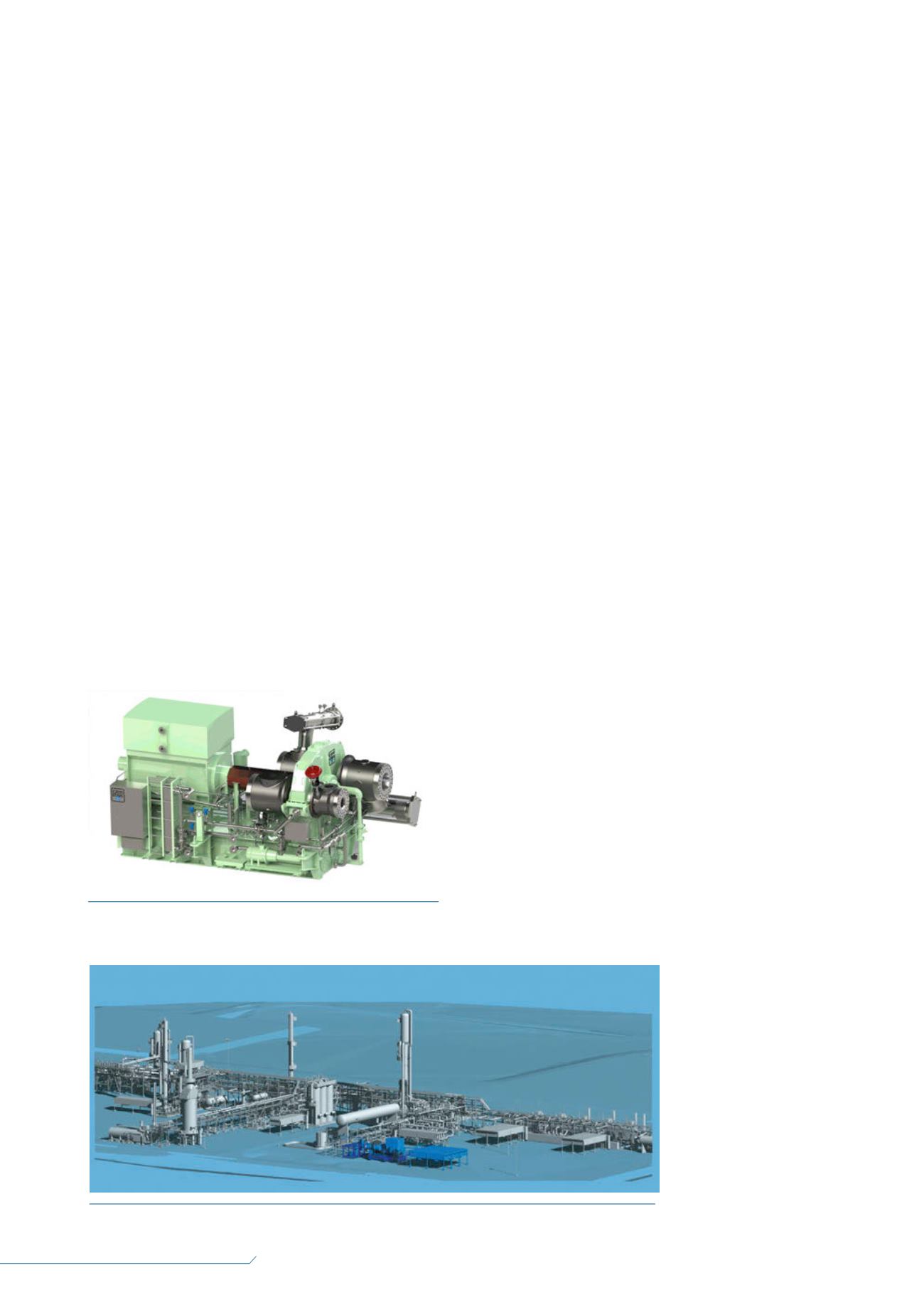
Figure 2.
A Cryostar compander with three compressor
wheels and an expander wheel.


