


 18 / 60

16
April 2020
drive MLA, and is ready to deploy this new technology to
its product range, including LNG.
With the same objective to improve efficiency and
reduce lifecycle costs, TechnipFMC has developed a
systematic MLA drone inspection method that has
performed more than 20 inspections since 2018.
Conventional MLA control
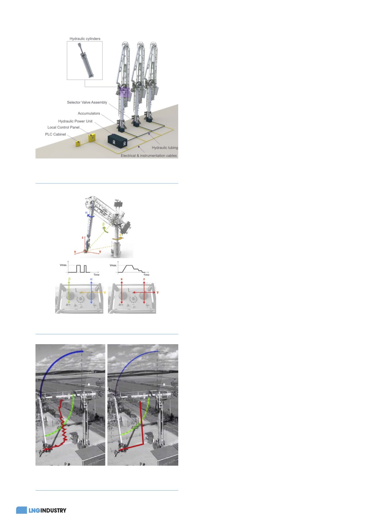
A typical hydraulic arrangement of a bank of MLAs
(Figure 1) consists of an electric motor powering a
hydraulic pump in a hydraulic power unit (HPU) and
providing pressure hydraulic oil to a network of hydraulic
tubing and hydraulic valves, which is converted into
mechanical energy. Hydraulic accumulators may be used
to provide hydraulic energy in case of electrical power
blackouts.
The three main rotary motions of the MLA – slewing,
inboard luffing and outboard arm luffing – are actuated
with hydraulic cylinders. In the majority of cases, the HPU
provides a constant hydraulic flow to each actuator, which
is controlled with a solenoid type valve (i.e. ‘on’ or ‘off’). A
single-speed motion is then achievable (i.e. ‘stop’ or
‘full speed’). The HPU may be fitted with a two-level flow
setting (‘low’ and ‘high’), allowing the operator to
manoeuvre the MLA at a reduced single-speed motion.
Using a remote control unit, the operator controls
each rotary motion – slewing, inboard luffing and
outboard arm luffing – to move the MLA connection
flange at the desired position, e.g. for
connection/disconnection to or from the ship manifold. ln
practice, controlling the MLA connection flange position is
not easy, requiring intensive training for the operator.
Plus, as the motions are generated by actuators with the
on-off control at a fixed speed, the MLA movements are
jerky and inexact.
Terminals and refineries with high operator turnover
may come to a situation where operators have limited or
no training on loading arm operations. As such, equipment
damages may result with ill-trained operators controlling
the loading arms. For instance, seals could be damaged
from shocks with the ship’s flange or delays could result
from lengthy connection/disconnection operations.
Finally, when a ship is impacted by waves in an
exposed jetty or offshore, connecting a loading arm may
be nearly impossible. TechnipFMC supplies a field-proven
targeting system that enables connection/disconnection
operations under up to 2.5 m significant wave height (Hs)
conditions. However, the system is overkill for terminals
only slightly exposed to waves.
Improved control
With conventional on-off hydraulics, the operator directly
commands the MLA rotations – slewing, inboard arm
luffing and outboard arm luffing – to indirectly control
the MLA connection flange. TechnipFMC’s Easy Drive
allows the operator to directly command the rectilinear
motions of the MLA connection flange – right/left,
forward/back, up/down – and indirectly act on the
MLA rotations through a controller. Based on a current
MLA position provided by angular sensors measuring
the angle of each MLA rotation (slew, inboard arm and
outboard arm) and the targeted rectilinear direction and
Figure 1.
Conventional hydraulic arrangement of a bank of
marine loading arms (MLAs).
Figure 2.
Conventional (left) versus Easy Drive (right)
remote control unit.
Figure 3.
Conventional (left) versus Easy Drive (right) MLA
connection flange trajectories.