24
LNG
INDUSTRY
JULY
2016
availability, each cycle typically must have two parallel
compressor sets, which is a disadvantage for small plants.
SMR uses a similar mixture of light hydrocarbons and
nitrogen as refrigerant. The process is simpler and easier to
operate, each liquefaction train beingmade of one refrigerant
cycle, with power consumption approximately 300 kWper kg/hr
of LNG produced. In this case, a single liquefaction cycle will
consist of at least two parallel compressor sets so that even if one
is offline, the plant will still be able to produce at 50%capacity.
DNE employs a refrigerant constituted by pure gaseous
nitrogen expanded via gas expanders at two different pressure
and temperature levels. The process is considered the simplest to
operate as each liquefaction train is made of one refrigerant cycle,
with power consumption approximately 450 kWper kg/hr of
LNG produced. If precooling is applied, power consumption can
be reduced by approximately 10%. Here too, a single liquefaction
train will typically consist of at least two parallel compressor sets,
and if one is offline, the plant will still be able to produce at 50%
capacity or more.
Refrigerant make-up
The following conclusions have been drawn under the
assumption that themixed refrigerant (MR) process requires
natural gas liquids (NGL) recovery and fractionation to produce
a stock of the refrigerant make-up to be held onboard the FLNG
vessel.
Driver selection
When selecting the refrigerant compressor drivers, it must be
considered that some gas turbines have a low starting torque and
are, therefore, difficult to start up from settle out conditions. This is
mainly an issue whenMR is used as the refrigerant, as venting the
refrigerant is costly and environmentally undesirable. In the case
of DNE, the venting of nitrogen is acceptable.
Hull
If MR technology is selected, then hull storage will also need
to include space for the refrigerant make-up inmultiple tanks.
Storage will also be required if condensate or LPG are to be
produced, based on the same principles as for LNG (parcel size,
plus buffer). Voids, ballast, machinery spaces and slop tanks are
also included in themodel.
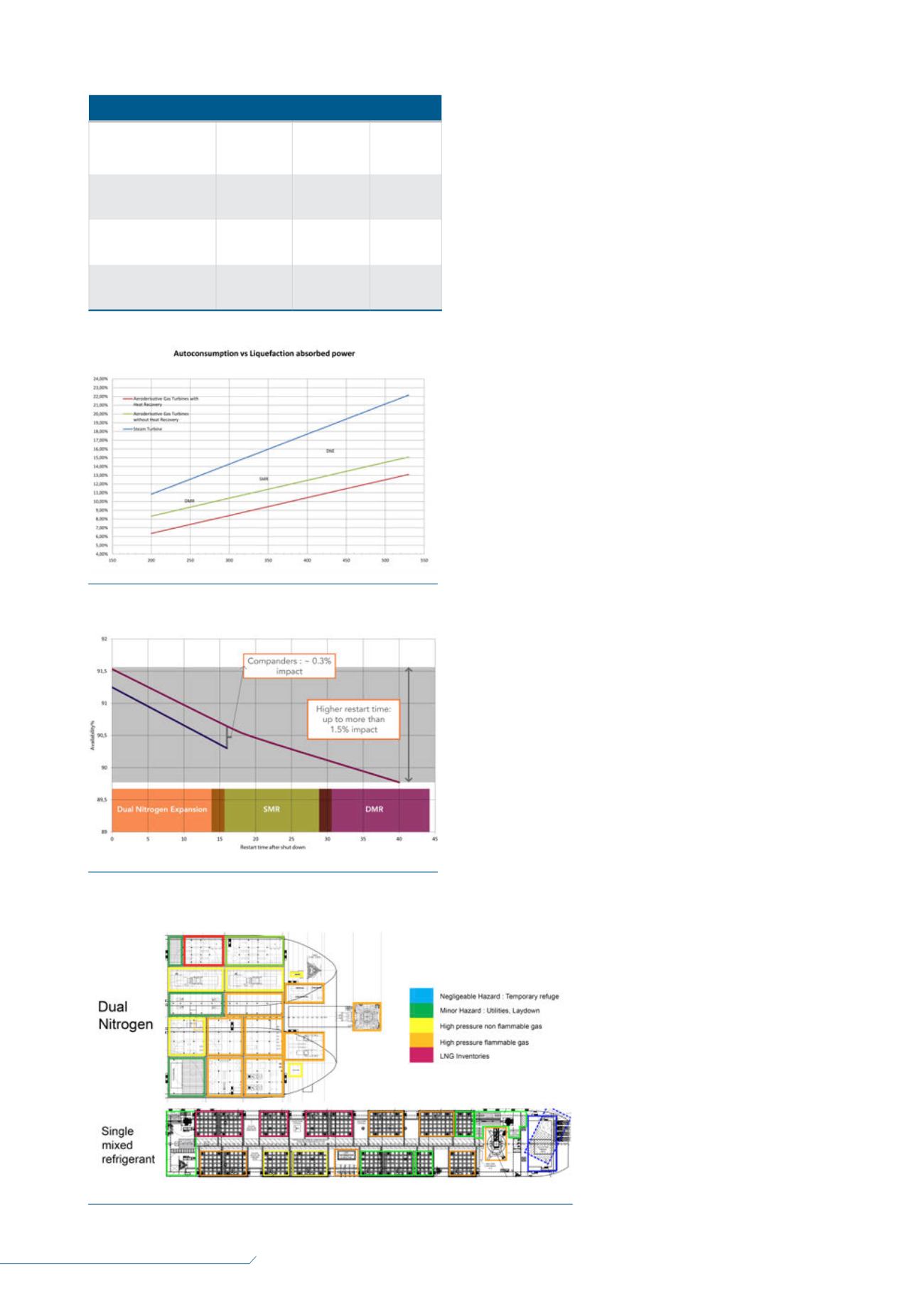
Efficiency
Selection of the process technology will obviously affect the
plant’s fuel consumption. However, as shown in Table 1, driver
selection will also play an important role in fuel consumption. For
example, Figure 1 shows that applying the dual nitrogen scheme
with an efficient driver plus heat recovery
will result in an overall fuel consumption
similar to that obtained using a DMRwith
steam turbines. It must also be noted that the
majority of onshore LNG plants use heavy
industrial gas turbines, which offer efficiency
comparable with that of steam systems.
Availability – impact
of restart time
When calculating annual production
capacities, the results of a sensitivity study
were used to define availability, as shown
in Figure 2. Here, the overall availability of
Table 1.
Mechanical drivers used in the parametric study
Refrigeration turbine
model number
LM2500+G4 LM6000PC
(PG)
RR Trent 60
WLE
ISO rated power (MW) 30.46
43.08 (50.4) 58.00
Efficiency at ISO
conditions (%)
39.5
41.2 (41.3)
41.8
Power at 25°C (MW)
28.27
39.97 (46.77) 53.82
Figure 2.
Availability vs restart time.
Figure 3.
Safety classification of modules for different liquefaction technologies.
Figure 1.
Impact of driver selection on fuel consumption.


