18
LNG
INDUSTRY
JULY
2016
The site specific gas reserves available, the size of the
production plant and the project objectives are key drivers for
selecting the most appropriate liquefaction process. There are
LNG liquefaction processes that use pure gas as refrigerants, or a
composition of different gases, called mixed refrigerants (MR).
Depending on gas properties and the amount of refrigerant
to be compressed, the compressor-inclusive drive system
comprising the compression string must be developed. As these
compression strings are key components in the LNG production
chain, it is essential to carefully evaluate the available
alternatives as early as possible.
Another important decision is the type of power to integrate
into the plant. A lot of energy is required to liquefy natural gas. In
most cases, the feed gas is used for the gas turbine, which
operates as either a mechanical drive or generator drive.
Electrical drivers in combination with the power from a
combined cycle power plant could also be considered for the
main liquefaction compressors.
For energy transfer from the gas source to refrigerant
compression, the Dresser-Rand business offers highly efficient
products and solutions for such a ‘power-to-compression’
system.
Siemens’ recent acquisitions of Dresser-Rand and the
aeroderivative gas turbine product portfolio from
Rolls-Royce Energy has resulted in a wider selection of both
drivers and compressors for all plant sizes. Equipment options
include the main liquefaction unit, amine unit, booster machine,
controls, and water treatment facility, etc.
When selecting the primary energy source for an LNG
production process, the goal is always to select the source that
offers the most efficient solution, regardless of what liquefaction
process is being considered by the owner.
In the past, the LNG industry primarily used steam turbine
drivers, but the steam process efficiency is often low at
approximately 26%. Project owners are increasingly turning to
electrical motor and gas turbine drives.
Unless the owner can secure a low price for power
(US$/kWh) and the level of power to meet peak facility demand
early in the project, the aeroderivative gas turbine solution
typically is the most attractive option. Electrical motors do not
necessarily reduce greenhouse gas (GHG) emissions if powered
by a combined cycle gas plant. However, emissions would be
lower if powered by a combined heat and power (CHP) or a
renewable/hydro-electric facility. While there are pros and cons
to each option, having access to alternative solutions can
provide peace of mind when planning a new LNG plant.
Melkøya LNG plant
In many cases, the electrical variable speed drive system (VSDS)
offers the highest degree of flexibility in order to fulfill all of
the process duty requirements of an LNG plant. Such systems
are available up to 90 MW. VSDS design concepts are usually
evaluated early in the project stage with a goal to optimise
the overall LNG plant solution and to avoid interharmonics in
operating speed range.
In principle, generated harmonic torque oscillations may
have an essential impact on the torsional vibration behaviour of
the entire train. Dynamic and accurate speed control via
electronic variable speed controllers is possible.
The VSDS allows for a soft start of the unit. It also provides a
torque that allows the compressor to restart from settle-out
pressure, regardless of process volume flow. Consequently, the
driver and compressor manufacturers must carry out a detailed
analysis to examine the expected operating condition of the
rotating equipment. Close collaboration of the driver and
compressor manufacturers in designing and engineering a VSDS
driven train is essential.
One example comes from the state-owned Norwegian oil
and gas company, Statoil, which developed the huge Snøhvit
natural gas field in the Barents Sea, approximately 140 km off
the North Norwegian coast. Due to the remoteness of the field,
Statoil decided to move large volumes of natural gas via
pipelines to Melkøya Island near Hammerfest, Norway, where
the gas is liquefied for export.
Reliable turbomachinery with minimal downtime was a key
requirement for the Melkøya LNG plant. For this project, several
refrigerant compressors are used at various stages of the gas
liquefaction process for CO
2
re-injection and driven by massive
65 MWVSDS electric motors.
Manufactured for the specific conditions that prevail in the
Arctic region, the compressors were designed for ambient
temperatures as low as -22°C and include a variety of features,
such as:
Glass reinforced plastic water lines.
High quality stainless steel materials.
Winterisation with heat tracing and weather protection.
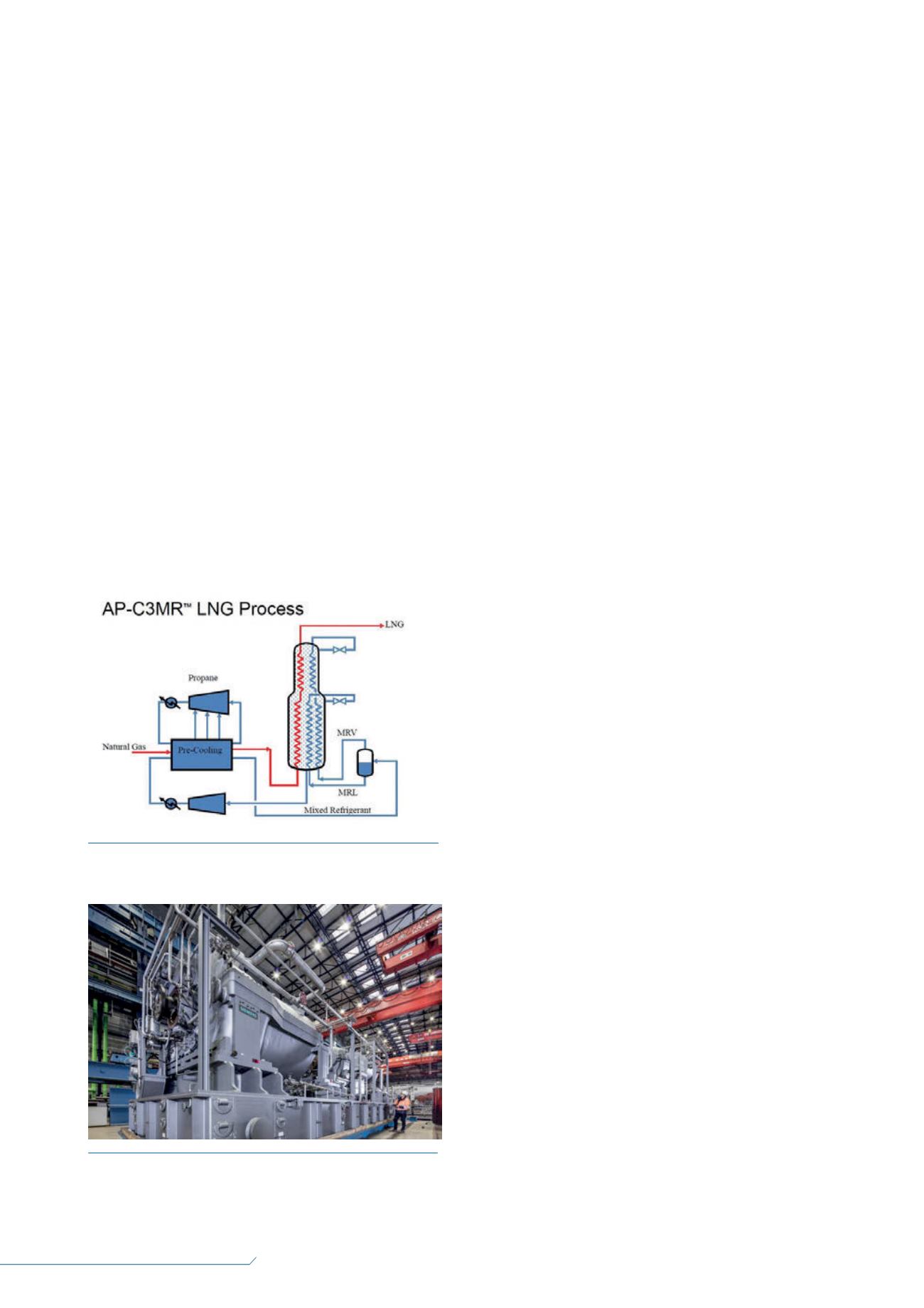
Figure 2.
An example of a typical LNG process set-up (source:
Air Products and Chemicals Inc.).
Figure 3.
In order to liquefy natural gas, it has to be cooled to
approximately -160°C. Siemens constructs the large liquefaction
compressors required for this process (source: Siemens).


