84
LNG
INDUSTRY
MARCH
2016
Membrane systems
Technigaz designed a membrane type atmospheric LNG
containment systemwith a corrugated stainless steel primary
membrane supported by wooden boxes filled with insulation
material. A secondary cryogenic barrier, also supported
by wooden boxes filled with insulation material, provides
containment of the cryogenic cargo in case the primary
membrane develops a leak. The characteristic corrugations in
the primary membrane allow for the shrinkage of metal under
cryogenic temperatures. This design, identified as the Mark I,
was soon superseded by improved versions and is currently
available as the Mark III series from a number of shipyards in
South Korea and Japan. The Mark V series will soon be put into
production, replacing the current Triplex secondary barrier with
a corrugated stainless steel secondary barrier.
Compatriot, Gaztransport, designed a similar system
consisting of a primary membrane supported by insulation in
plywood boxes and a secondary membrane, also supported by
insulation in plywood boxes. This systemwas called the No 88
system and featured a primary and secondary membrane of a
steel alloy with a negligible contraction coefficient.
Improvements have been made over the years and the current
system is the No 96, which is being used in LNG carriers under
construction in South Korea and China.
After years of competition, Gaztransport and Technigaz
merged to form GTT in 1994. GTT has been developing and
promoting both membrane type containment systems in
parallel, and has licensed these systems to all major LNG carrier
builders around the world.
The main advantage of the membrane type containment
systems is their prismatic shape, which allows these systems to
use the space available within the hull of the LNG carrier to a
very high degree. With the cargo tanks recessed deep inside the
hull under a low trunk deck, membrane type LNG carriers do not
require a high deckhouse to have good visibility. In France, GTT
proposed membrane type LNG fuel tanks for a newbuilding
from Brittany Ferries. Unfortunately, this project was put on hold
for non-technical reasons.
However, both of the membrane systems are vulnerable to
sloshing damage. Sloshing is the motion of the LNG cargo in
the tanks as a result of the effect of waves and wind on the
vessel. In certain circumstances, waves occur in the LNG cargo.
Upon impact with the tank walls, this can cause damage to the
primary barrier and the boxes supporting the primary
membrane. To counter the risk of sloshing damage, GTT advises
that ships are operated with tank levels of more than 90% or
less than 10%. For applications that require part load operations,
such as floating storage and regasification units (FSRU),
membrane systems with specially reinforced boxes have been
developed.
The Moss system
The Moss spherical LNG containment system does not
experience sloshing issues. Its aluminium spheres have
sufficient structural strength to withstand LNG wave impact due
to the interaction between the cargo and the ship’s motion. The
Moss system does not require a full secondary barrier; there
is only a small drip tray below the spheres to catch any liquid
leaking. The design philosophy behind the Moss system is that
the tank should be designed to be strong enough so that cracks
should not develop in the tanks over the lifetime of the vessel.
The structural strength of the containment system is exactly
the reason why old Moss vessels are popular candidates for
conversion to FSRUs or even floating LNG (FLNG) production
plants.
However, the Moss vessels have a low hull space utilisation
rate. The sheers are mounted on the deck of the vessel by way
of an equatorial ring, which means that half the sphere
protrudes above the deck. While this makes for the
characteristic silhouette of the Moss carrier, it also necessitates
a high deckhouse to ensure adequate line of sight from the
bridge. The low hull space utilisation means that a Moss carrier
has a higher gross tonnage
than membrane carriers of similar
cargo capacity, which translates into higher port and fairway
dues and higher tonnage taxes.
The SPB system
The fourth LNG cargo containment system – the SPB system
– combines the advantages of the membrane system and
the Moss system, while also addressing the disadvantages
of both systems. The prismatic shape of the tanks ensures
a high hold space utilisation rate and a low air draft, while
the solid aluminium construction with a
centreline bulkhead and transverse swash
bulkheads reduces liquid motion in the
tanks and minimises the risk of sloshing
damage, even in part load conditions.
The high price of this system originally
prevented wide spread adoption, but in
2014, Japan Marine United Corp. (JMU) – the
successor to SPB designer IHI Corp. –
secured tank orders for four 165 000 m
3
LNG
carriers. With possible licensing overseas,
the SPB system could become a serious
contender in the LNG containment system
arena. In Japan, JMU has already carried out
a study with a shipyard into the feasibility of
SPB tanks as LNG fuel tanks.
LNG as fuel
LNG carriers have long been using the
boil-off gas (BOG) from their cargo tanks
as fuel for their engines. In 2000, the
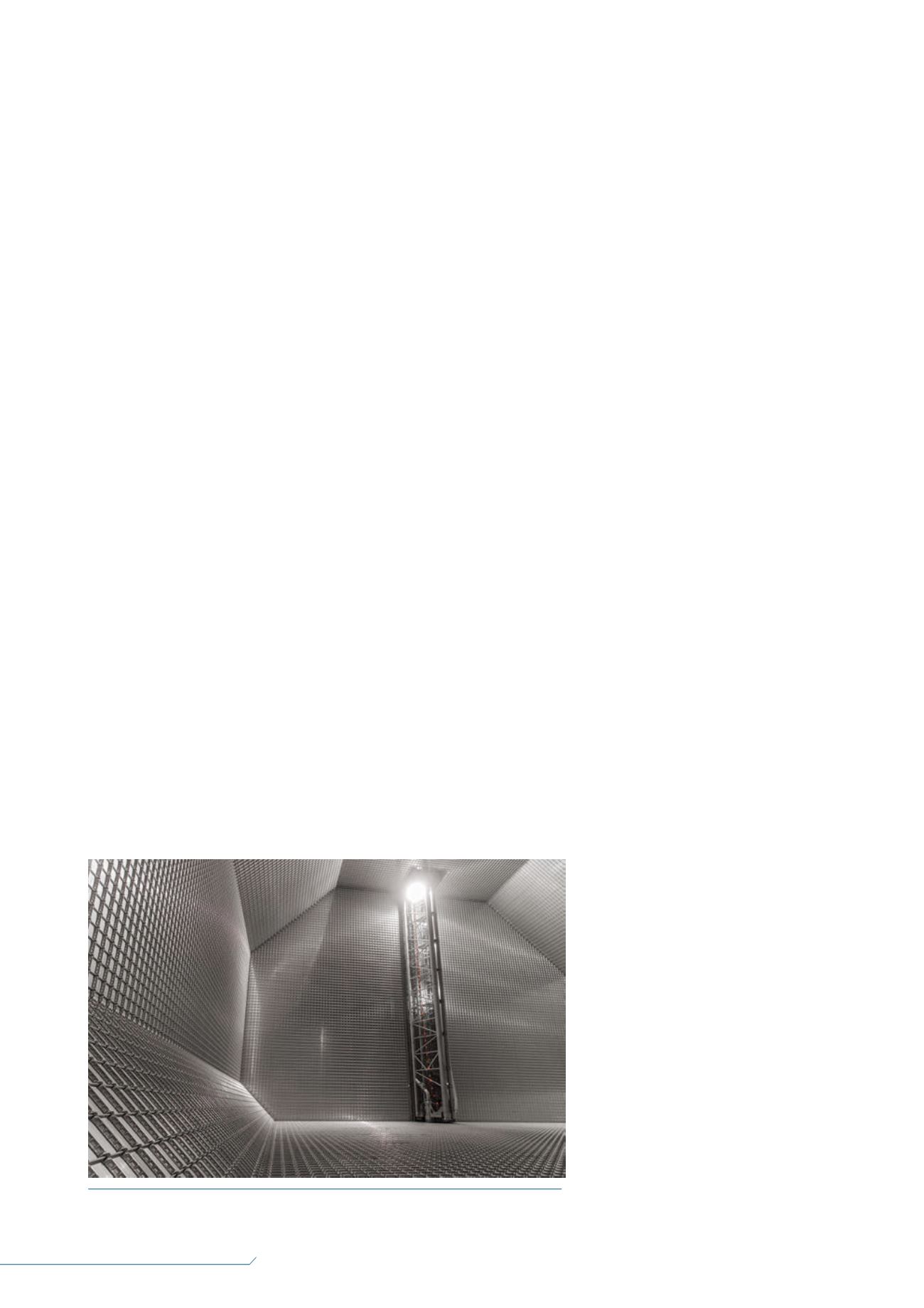
Figure 1.
View of the interior of a Gaztransport & Technigaz (GTT) Mark III LNG cargo
tank onboard an LNG carrier (source: GTT).


