62
LNG
INDUSTRY
OCTOBER
2016
pipes were rapidly doused in water, allowing the material
to fix the austenitic microstructure and obtain the required
set of mechanical properties. After descaling, the pipes
were straightened, pickled, cut to the required lengths, and
bevelled, as required for further welding.
The second step saw the mother pipes supplied from
the company’s hot formed shop, and reduced in ‘cold’
conditions to the required final size, either in one step or
in a number of intermediate steps, by means of pilgering
mills. After each of the cold forming steps, the tubes were
annealed in gas furnaces with temperatures of at least
1070°C and then pickled and passivated. Alternatively, the
tubes were bright annealed in a continuous hydrogen
furnace (Figure 2), allowing enhanced quality of the
surfaces. After the final forming, the tubes underwent
straightening, cutting to the required lengths, surface
finishing, and bevelling.
Quality of the production was checked in accordance
with the agreed test plan, which normally included visual
inspection and dimensional control, mechanical testing
for strength and robustness, flattening tests, ultrasonic
and eddy-current examination, and hydrotesting in order
to ensure structural integrity. Austenitic steels were
tested for resistance to intergranular corrosion, as in the
case of FLNG, according to Practice E of the ASTM A262
standard. Also, the material for sour environments was
checked against the requirement of the NACE 0175 and
ISO 15156 standards to decrease the risk of stress
corrosion cracking.
Materials control
Work on high quality production always begins with the
selection of raw materials. Strictly following requirements
for chemical composition within the limits given by the
reference standard is not typically enough. By controlling
the relative content of the alloying elements, it is possible
to limit the amount of ferrite in the austenitic matrix to
a narrow range, minimising instability in impact strength
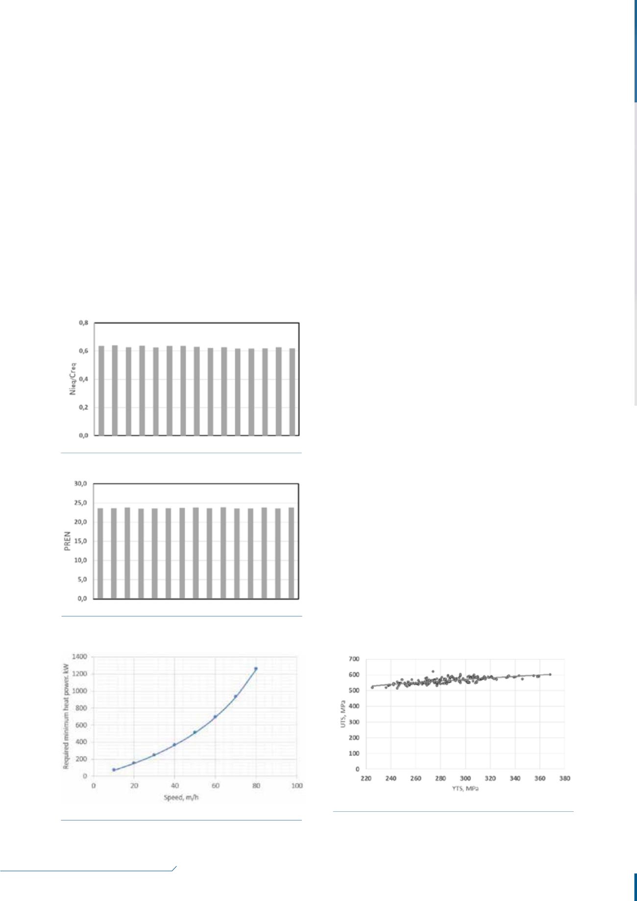
and corrosion properties. Figure 3 shows that the ratio of
Ni and Cr equivalents for the production heats was kept at
an average level of 0.63, with the variation not exceeding
1.5%. Another aspect of this exercise is in minimising the
variation of PREN. Figure 4 shows that the average PREN
was 23.7 and deviations were below 2%.
Heat treatment processes
Careful selection of heat treatment regimens is crucial for
the formation of the correct microstructure throughout
the entire wall thickness of the tube, allowing for the
necessary corrosion resistance and mechanical strength.
To achieve this, the material should be given the right
combination of heat input and soaking time for any heat
load in the furnace. Transient heat transfer calculations
show that, for continuous furnaces, the required
translation speed of the tubes is proportional to the heat
power, and inversely related to the total area of cross
sections of the load. Figure 5 presents an example of
calculations for a set of tubes, showing the calculated
heat power vs speed of the rollers of the furnace,
demonstrating that the dependency is not linear – faster
speeds require disproportionally higher heat inputs.
Figure 5.
Furnace heating power vs translation speed.
Figure 6.
Ultimate tensile strength (UTS) vs yield tensile
strength (YTS).
Figure 4.
Pitting resistance equivalent numbers (PREN).
Figure 3.
Nickel-to-chromium equivalent ratios.


