52
LNG
INDUSTRY
OCTOBER
2016
There are also practical considerations for the vessel
arrangement. A 200 ft
2
vane cannot be expected to operate at
peak efficiency if it is 5 ft wide and 40 ft tall. Such an arrangement
would almost certainly have poor flow distribution and be prone
to unstable operation. In general, holding dimensions within a
2:1 ratio is sufficient to promote uniform flow distribution.
The gas velocity within themain body of the vessel should not
exceed the design gas velocity of themist eliminator, as doing so
increases the risk of flowmaldistribution.
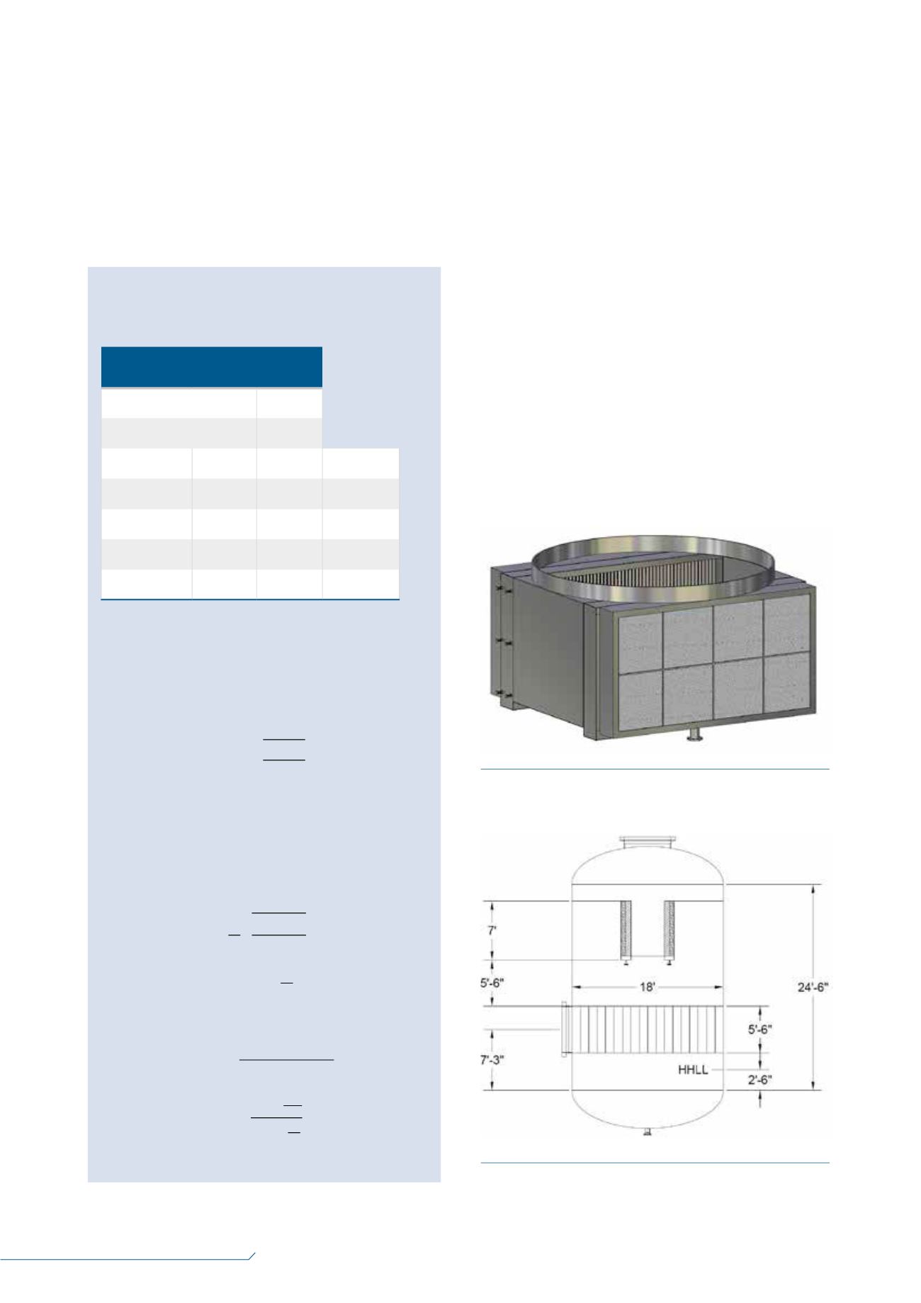
If an 18 ft dia. vessel is considered, and reasonable allowances
for the housing installation aremade, then a single vertical bank
would be approximately 13 ft tall.
Alternatively, the vane bank may be split into two 7 ft tall
parallel banks, as shown in Figure 1. This twin box arrangement
requires an 18 ft dia. x 24 ft x 6 in. high vertical vessel, shown in
Figure 2. This is a significant reduction from the 34 ft dia. traditional
design. A vane type inlet device has been included as a
recommended practice for this example. The detailed discussion
of inlet device type selection and design is outside the scope of
this article.
There are dimensional guidelines that relate the
disengagement space between the high high liquid level (HHLL),
inlet device, vane pack entrance, inlet chord area, outlet area, and
above the vane to the vessel outlet.
It is possible to retrofit an existing vessel with this
arrangement, but doing so frequently requires welding the
housing structure to the shell. The vertical height required often
makes this option impossible. The vane will not fit within the
space available.
The twin box arrangement provides excellent capacity and
mist separation efficiency, but requires significant vertical height.
Figure 1.
Sulzer twin box vane with preconditioner.
Figure 2.
Twin box vane arrangement.
Low pressure MR suction
knock out
Table 1.
Low pressure suction knock
out design basis
Operating temperature
-45°C
Operating pressure
35.5 psia
Gas
Liquid
Units
Mass flowrate 3 million 30 000 lb/h
Density
0.30
36.2
lb/ft
3
Viscosity
0.008
0.20
cP
Surface tension N/A
15
Dyne/cm
Performance targets:
•
Removal of 99% of 10
µ
m droplets.
•
Pressure drop: 1.0 psi maximum.
Traditional design practice uses the Souders-Brown
equation to define a maximum design velocity:
ch 24, 2016
ign 2Stimization oI a /ow 3ressure Mi[eG 5eIrigerant Suction KnocN 2ut 'rum
Low Pressure Mixed R frigerant Suction Drum receives refrigerant vapor flow from the main
genic heat exchanger and sep rates entrained liquids to protect the mixed refrigerant
pressor from damage. Operationally, the LP MR Suction Drum is characterized by high gas
me with low liquid flow, ypically less than 1% by mass. The high gas flow drives the size
irements of the vessel, and as a result, these vessels tend to be quite large. This service is a
d candidate for optimization through careful selection of process internals.
sider the following design basis.
LP MR Suction Knock Out Design Basis
rating Temperature
-45°F
rating Pressure
35.5 psia
Gas
Liquid
Units
s Flow Rate
3,000,000
30,000
Lb / h
sity
0.30
36.2
Lb / ft
3
osity
0.008
0.20
cP
ace Tension
N / A
15
Dyne / cm
ormance Targets
oval of
99
% of
10
Micron droplets.
sure Drop
1.0 psi
Max
itional design practice uses th Souders-Brown quation to define a maximum design velocity:
ݒ
= ݇ඨ
ߩ
െ
ߩ
ீ
ߩ
ீ
GPSA Data Book section on Separators recommends that the gas load factor k = 0.28 ft. / s
compressor suction scrubber in a vertical drum with a wire mesh mist eliminator. We then
titute the gas and liquid density from above and find the maximum design velocity is
ݒ
= 0.2ͺ ඨ 36.2 െ 0.3 0.3
ݒ
= 3.063
minimum required flow area is
= ܸ݈
ݑ
݉ ݅ܿ ݈
ݓ
ܸ ݈ܿ݅
ݕ
The GPSA Data Book section on Separators
recommends that the gas load factor k = 0.28 ft/sec. for a
compressor suction scrubber in a vertical drumwith a wire
mesh mist eliminator. Next, substitute the gas and liquid
density from above to find that the maximum design
velocity is:
24, 2016
n 2Stimization oI a /ow 3re sur Mi[eG 5 Irigerant Sucti n KnocN 2ut 'rum
ow Pressure Mixed Refrigerant Suction Drum receives refrigerant vapor flow from the main
enic heat exchanger and sep rates entrained liquids to protect the mixed refrigerant
ressor from damage. Operationally, the LP MR Suction Drum is characterized by high gas
e with low liquid flow, typically less than 1% by mass. The high gas flow drives the size
ements of the vessel, and as a result, these vessels tend to be quite large. This service is a
candidate for optimization through careful selection of process internals.
der the following design basis.
LP MR Suction Knock Out Design Basis
ting Temperature
-45°F
ting Pressure
35.5 psia
Gas
Liquid
Units
Flow Rate
3,000,000
30,000
Lb / h
ty
0.30
36.2
Lb / ft
3
sity
0.008
0.20
cP
e Tension
N / A
15
Dyne / cm
mance Targets
val of
99
% of
10
Micron droplets.
ure Drop
1.0 psi
Max
ional design practice uses the Souders-Brown equation to define a maximum design velocity:
ݒ
= ݇ඨ
ߩ
െ
ߩ
ீ
ߩ
ீ
PSA Data Book section on Separators recommends th t the gas load factor k = 0.28 ft. / s
ompressor suction scrubber in a vertical drum with a wire mesh mist eliminator. We then
tute the gas and liquid density from above and find the maximum design velocity is
ݒ
= 0.2ͺ ඨ 36.2 െ 0.3 0.3
ݒ
= 3.063
inimum required flow area is
= ܸ݈
ݑ
݉ ݅ܿ ݈
ݓ
ܸ ݈ܿ݅
ݕ
ch 24, 2016
ign 2Stimization oI a /ow 3ressure Mi[eG 5eIrigerant Suct on KnocN 2ut 'rum
Low Pressure Mixed Refri erant Suction Drum receives refrigerant vapor flow from the main
genic heat xchanger and separates ent ained liquids to protec the mixed refrigerant
pressor from damag . Operationally, the LP MR Suction Drum is characterized by high gas
me with low liquid flow, typically ess than 1% by mass. The hig g s flow drives the size
irements of the vessel, and as a result, these ves els tend to be quite la g . T is service is a
candidate for optimization through careful selection of proc ss internals.
sider the following design basis.
LP MR Suction Knock Out Design Basis
rating Temperature
-45°F
rating Pressure
35.5 psia
Gas
Liquid
Units
s Flow Rate
3,000, 00
30,000
Lb / h
sity
0.30
36.2
Lb / ft
3
osity
0.008
0.20
cP
ace Tension
N / A
15
Dyne / cm
ormance Targets
oval of
99
% of
10
Micron droplets.
sure Drop
1.0 psi
Max
itional design practice uses the Souders-Brown equation to define a maximum design velocity:
ݒ
= ݇ඨ
ߩ
െ
ߩ
ீ
ߩ
ீ
GPSA Data Book section on Separators recommends that the gas load factor k = 0.28 ft. / s
compressor suction scrubber in a vertical drum with a wire mesh mist eliminator. We then
titute the gas and liquid density from above and find the maxi um design velocity is
ݒ
= 0.2ͺ ඨ 36.2 െ 0.3 0.3
ݒ
= 3.063
minimum required flow area is
= ܸ݈
ݑ
݉ ݅ܿ ݈
ݓ
ܸ ݈ܿ݅
ݕ
The minimum required flow area is:
rch 24, 2016
sign 2Stimizati n oI a / w 3 essure Mi[eG 5 Irigerant Suctio K ocN 2ut 'rum
Low Pressure Mixed Refrigerant Suc io Drum receives refrigerant v por flow from the main
ogenic heat exchanger and sep rates e trained liquids to prote t the mixe efrigerant
press r from amage. Operationally, the LP MR Suc ion Drum i charact rized by high gas
u w th low liquid flow, typically less than 1% by mass. Th high gas flow driv s th ize
uirements f the vessel, and as a result, these vessels tend to be quite large. This service is a
d candidate for optimization through careful selection of process internals.
nsider the following design basis.
LP MR Suction Knock Out Design Basis
erating Temperatur
-45°F
erating Pressure
35.5 psia
Gas
Liquid
Uni s
s Flow Rate
3,0 ,000
30, 00
Lb / h
nsity
0.30
36.2
Lb ft
3
cosity
0.008
0.20
cP
rface Tension
N / A
15
Dyne / cm
rformance Targets
moval of
99
% of
10
Micron droplets.
ssure Drop
1.0 psi
Max
ditional design practice u es the S uders-Brown equation to define maximum design velocity:
ݒ
= ݇ඨ
ߩ
െ
ߩ
ீ
ߩ
ீ
GPSA Data Book section on Separators recommends that the gas load factor k = 0.28 ft. / s
a compressor suction scrubber in a vertical drum with a wire mesh mist eliminator. We then
stitute the gas an liquid density from above and find the maximum design velocity is
ݒ
= 0.2ͺ ඨ 36.2 െ 0.3 0.3
ݒ
= 3.063
minimum required flow area is
= ܸ݈
ݑ
݉ ݅ܿ ݈
ݓ
ܸ ݈ܿ݅
ݕ
ry 24, 2016
Optimization of a Low Pressure Mixed Refrigerant Suction Knock Out Drum
of 7
= 2777
3
3.063
= 907
2
resultant vessel diameter is nearly 34 ft.! There must be a better solution.


