50
LNG
INDUSTRY
OCTOBER
2016
the base of columns, particularly packed columns of large
diameter, as well as trayed columns. Failure to do so can
cause serious maldistribution of gas (and, consequently,
liquid) over the column’s cross section, which will lead to
poor treating performance.
A useful pair of tools for assessing maldistribution,
whether gas, liquid, or both, is mass transfer rate-based
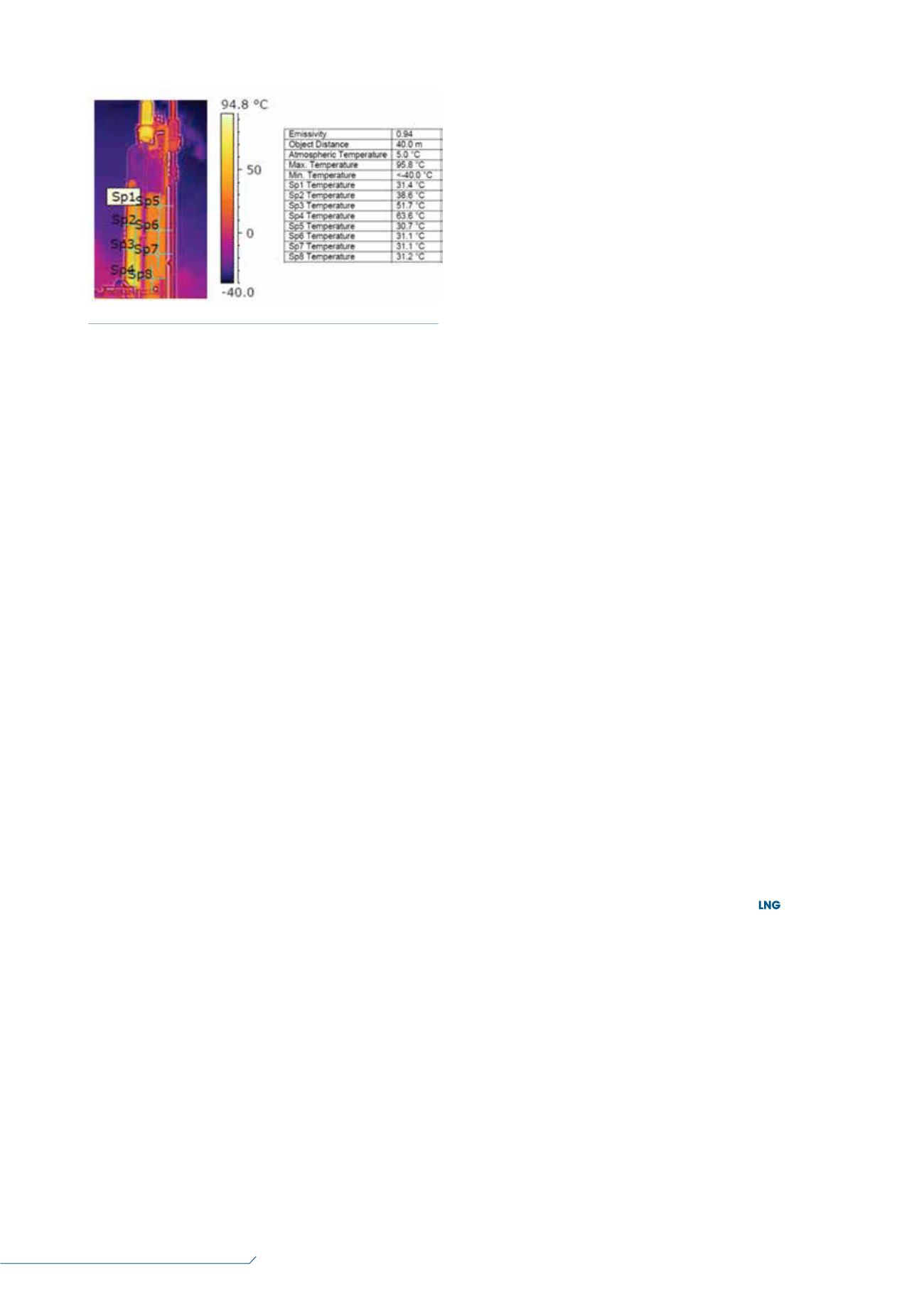
simulation and thermal imaging of the tower. Figure 3
shows a thermal image of the upper two-thirds of an
absorber in an ammonia plant using a piperazine-promoted
MDEA-based solvent (the lower third could not be imaged
from this position because of the proximity of other
equipment). The position of the gas inlet nozzle was behind
the column as it is seen in the photograph and towards its
left side. As the table in Figure 3 shows, the temperature
profile along the height of the absorber exhibited a distinct
bulge along its left side (above the gas inlet nozzle) near
the bottom of the image, but an almost uniform
temperature (and equal to the lean solvent temperature)
on the wall opposite the nozzle. This column was suffering
from poor gas distribution. It is certainly not normal to see
great temperature asymmetries around the periphery of a
correctly operating column. Instead of trying to match the
plant measured treating performance by tuning an obtuse
parameter, such as tray efficiency or residence time per
theoretical stage, a true mass transfer rate model would
reveal that the wetted interfacial area would need to be
derated.
Corrosion
Missing and corroded trays can be hard to diagnose
without expensive gamma scans. However, if tray damage
is suspected, a thermal scan may show anomalies in
longitudinal temperature distribution, especially when
compared with mass transfer rate-based simulation.
Because a mass transfer rate model uses actual trays, not
idealisations, and assumes that all trays are operating
properly, simulation of a column with fewer operating trays
than it is supposed to contain may allow the simulation
to reproduce tower performance data. Similarly, reducing
the effective interfacial area in the packed bed will allow
the simulation to reproduce performance data if packing is
missing or badly damaged. Comparison with thermal scans
may also provide further evidence of packing or tray damage.
On the other hand, moderate foaming can actually
cause better performance than expected because of the
increased interfacial area consequent to the presence of
foam. Severe foaming, however, always degrades tower
performance. If a mass transfer rate-based simulation
needs 20% or 30% more area than physically provided by
the packing as simulated, foaming may be indicated.
A leaking heat exchanger, especially a cross exchanger,
can result in treating being missed by a wide margin if the
leak is from the rich side to the lean side of the exchanger
(as it most often is). Treating is usually fairly sensitive to
lean solvent loading of acid gas. The simplest diagnosis is
rate-based simulation of the regenerator, followed by a
comparative measurement of the solvent lean loading as it
enters the absorber and, if possible, upstream of the
exchanger as well. It should be noted, however, that lean
solvents can be hard to assess properly because H
2
S tends
to oxidise to thiosulfate in the presence of air. Again,
simulation will reveal whether the measured lean loading
is capable of satisfactorily treating the raw gas. In one
instance, mass transfer rate-based simulation pointed an
operator to resample around a lean/rich exchanger with
bottles pre-purged with nitrogen. The leak was confirmed
through sampling only after taking these and other
precautions to eliminate oxygen contamination.
Amine units can also fall short because of
instrumentation malfunctions caused by equipment fouled
not just by corrosion products, but also by materials
injected into the system for various reasons. Examples of
injected foreign materials include corrosion inhibitors,
antifoams, and oxygen scavengers. These materials
degrade and form gels and assorted sticky substances that
can plug level and flow meter pressure taps, resulting in
false readings. Suspended particulates erode orifice plates
and also lead to false readings.
Conclusion
The CO
2
absorbers in LNG plants (and other deep CO
2
removal applications, such as syngas) can fail to meet
expectations for a wide variety of reasons. The most
common ones have been discussed in ths article. The
overriding lesson is that genuine mass transfer rate-based
simulation, coupled (where appropriate) with thermal
imaging, is an excellent tool not just for design, but for
troubleshooting and plant monitoring as well.
References
1. WEILAND, R., SCHULTES, M., PILLING, M.,
PORTILLO, J., SUMMERS, D., SHIVELER, G.,
DUSS, M., STEWART, E., and PRADERIO, A.,
‘Sensitivity of Treating Plant Performance to Tower
Internals’, paper presented at the Laurance Reid Gas
Conditioning Conference, Norman, Oklahoma, US,
(21
–
24 February 2016).
2. WEILAND, R. H., and HATCHER, N. A.,
‘Foundations of Failure’,
Hydrocarbon Engineering
,
(December, 2011), pp. 57 – 59.
3. SIEDER, G., KATZ, T., and HEARN, J., ‘How Glycols
Affect the Acid Gas Removal Process’, PTQ, Q4, (2013).
4. COOPER, E., and WEILAND, R., ‘Reducing CO
2
Slip from the Syngas Unit of an Ammonia Plant’,
paper presented at Nitrogen + Syngas 2016, Berlin,
Germany, (29 February – 3 March 2016).
Figure 3.
Thermal image of a CO
2
absorber.


